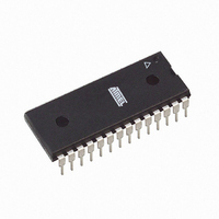
AT27C512R-70PU Atmel, AT27C512R-70PU Datasheet - Page 9

AT27C512R-70PU
Manufacturer Part Number
AT27C512R-70PU
Description
IC OTP 512KBIT 70NS 28DIP
Manufacturer
Atmel
Specifications of AT27C512R-70PU
Format - Memory
EPROMs
Memory Type
OTP EPROM
Memory Size
512K (64K x 8)
Speed
70ns
Interface
Parallel
Voltage - Supply
4.5 V ~ 5.5 V
Operating Temperature
-40°C ~ 85°C
Package / Case
28-DIP (0.600", 15.24mm)
Organization
64 K x 8
Access Time
45 ns
Supply Voltage (max)
5.5 V
Supply Voltage (min)
4.5 V
Maximum Operating Temperature
85 C
Interface Type
Parallel
Minimum Operating Temperature
- 40 C
Mounting Style
Through Hole
Capacitance, Input
4 pF
Capacitance, Output
8 pF
Current, Input, Leakage
±1 μA
Current, Operating
20 mA (Read)
Current, Output, Leakage
±5
Density
512K
Package Type
PDIP
Temperature, Operating
-40 to +85 °C
Time, Access
70 ns
Time, Address Setup
2
Time, Fall
20 ns
Time, Rise
20 ns
Voltage, Esd
2000 V
Voltage, Input, High
5.5 V (Read)
Voltage, Input, Low
0.8 V (Read)
Voltage, Output, High
2.4 V (Read)
Voltage, Output, Low
0.4 V (Read)
Voltage, Supply
5 V
Lead Free Status / RoHS Status
Lead free / RoHS Compliant
Available stocks
Company
Part Number
Manufacturer
Quantity
Price
Company:
Part Number:
AT27C512R-70PU
Manufacturer:
ATMEL
Quantity:
9 280
Company:
Part Number:
AT27C512R-70PU
Manufacturer:
ATMEL
Quantity:
44 366
Part Number:
AT27C512R-70PU
Manufacturer:
ATMEL/爱特梅尔
Quantity:
20 000
18. Rapid Programming Algorithm
0015O–EPROM–12/07
A 100 µs CE pulse width is used to program. The address is set to the first location. V
raised to 6.5V and OE/V
100 µs CE pulse without verification. Then a verification/reprogramming loop is executed for
each address. In the event a byte fails to pass verification, up to 10 successive 100 µs pulses
are applied with a verification after each pulse. If the byte fails to verify after 10 pulses have
been applied, the part is considered failed. After the byte verifies properly, the next address is
selected until all have been checked. OE/V
are read again and compared with the original data to determine if the device passes or fails.
PP
is raised to 13.0V. Each address is first programmed with one
PP
is then lowered to V
IL
and V
AT27C512R
CC
to 5.0V. All bytes
CC
is
9


