DS1250WP-100IND+ Maxim Integrated Products, DS1250WP-100IND+ Datasheet - Page 8
DS1250WP-100IND+
Manufacturer Part Number
DS1250WP-100IND+
Description
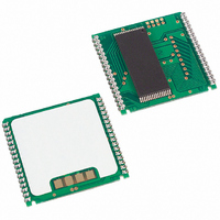
IC NVSRAM 4MBIT 100NS 34PCM
Manufacturer
Maxim Integrated Products
Datasheet
1.DS1250WP-150.pdf
(9 pages)
Specifications of DS1250WP-100IND+
Format - Memory
RAM
Memory Type
NVSRAM (Non-Volatile SRAM)
Memory Size
4M (512K x 8)
Speed
100ns
Interface
Parallel
Voltage - Supply
3 V ~ 3.6 V
Operating Temperature
-40°C ~ 85°C
Package / Case
34-PowerCap™ Module
Lead Free Status / RoHS Status
Lead free / RoHS Compliant


8. If
9. Each DS1250W has a built-in switch that disconnects the lithium source until V
10. All AC and DC electrical characteristics are valid over the full operating temperature range. For
11. In a power-down condition the voltage on any pin may not exceed the voltage on V
12. t
13. t
14. DS1250 modules are recognized by Underwriters Laboratories (UL) under file E99151.
DC TEST CONDITIONS
Outputs Open
Cycle = 200ns for operating current
All voltages are referenced to ground
ORDERING INFORMATION
DS1250W-100+
DS1250WP-100+
DS1250W-100IND+
DS1250WP-100IND+
+Denotes a lead(Pb)-free/RoHS-compliant package.
*DS9034PC+ or DS9034PCI+ (PowerCap) required. Must be ordered separately.
PACKAGE INFORMATION
For the latest package outline information and land patterns, go to www.maxim-ic.com/packages.
“#”, or “-” in the package code indicates RoHS status only. Package drawings may show a different suffix
character, but the drawing pertains to the package regardless of RoHS status.
PACKAGE TYPE
the output buffers remain in a high-impedance state during this period.
the user. The expected t
time power is first applied by the user.
commercial products, this range is 0°C to +70°C. For industrial products (IND), this range is -40°C to
+85°C.
WR1
WR2
WE
and t
and t
PART
34 PCAP
32 EDIP
is low or the
DH1
DH2
are measured from
are measured from
WE
TEMP RANGE
-40°C to +85°C
-40°C to +85°C
DR
low transition occurs prior to or simultaneously with the
0°C to +70°C
0°C to +70°C
PACKAGE CODE
is defined as accumulative time in the absence of V
MDT32+6
PC2+5
CE
WE
going high.
going high.
TOLERANCE
8 of 9
3.3V ± 0.3V
3.3V ± 0.3V
3.3V ± 0.3V
3.3V ± 0.3V
AC TEST CONDITIONS
Output Load: 100 pF + 1TTL Gate
Input Pulse Levels: 0 to 2.7V
Timing Measurement Reference Levels
Input pulse Rise and Fall Times: 5ns
SUPPLY
OUTLINE NO.
Input: 1.5V
Output: 1.5V
21-0245
21-0246
PIN-PACKAGE
32 740 EDIP
34 PowerCap*
32 740 EDIP
34 PowerCap*
LAND PATTERN NO.
CC
CC
CC
CE
is first applied by
starting from the
.
Note that a “+”,
low transition,
GRADE (ns)
—
—
SPEED
DS1250W
100
100
100
100
Related parts for DS1250WP-100IND+
Image
Part Number
Description
Manufacturer
Datasheet
Request
R

Part Number:
Description:
IC NVSRAM 4MBIT 150NS 34PCM
Manufacturer:
Maxim Integrated Products
Datasheet:
Part Number:
Description:
IC NVSRAM 4MBIT 100NS 34PCM
Manufacturer:
Maxim Integrated Products
Datasheet:
Part Number:
Description:
IC NVSRAM 4MBIT 150NS 34PCM
Manufacturer:
Maxim Integrated Products
Datasheet:

Part Number:
Description:
Ds1250w 3.3v 4096k Nonvolatile Sram
Manufacturer:
Maxim Integrated Products, Inc.
Datasheet:
Part Number:
Description:
The DS1250W 3
Manufacturer:
Maxim
Datasheet:

Part Number:
Description:
IC NVSRAM 4MBIT 100NS 32DIP
Manufacturer:
Maxim Integrated Products
Datasheet:
Part Number:
Description:
IC NVSRAM 4MBIT 150NS 32DIP
Manufacturer:
Maxim Integrated Products
Datasheet:
Part Number:
Description:
IC NVSRAM 4MBIT 100NS 32DIP
Manufacturer:
Maxim Integrated Products
Datasheet:
Part Number:
Description:
IC NVSRAM 4MBIT 100NS 32DIP
Manufacturer:
Maxim Integrated Products
Datasheet:
Part Number:
Description:
IC NVSRAM 4MBIT 100NS 32DIP
Manufacturer:
Maxim Integrated Products
Datasheet:
Part Number:
Description:
IC NVSRAM 4MBIT 150NS 32DIP
Manufacturer:
Maxim Integrated Products
Datasheet:

Part Number:
Description:
MAX7528KCWPMaxim Integrated Products [CMOS Dual 8-Bit Buffered Multiplying DACs]
Manufacturer:
Maxim Integrated Products
Datasheet:
Part Number:
Description:
Single +5V, fully integrated, 1.25Gbps laser diode driver.
Manufacturer:
Maxim Integrated Products
Datasheet:
Part Number:
Description:
Single +5V, fully integrated, 155Mbps laser diode driver.
Manufacturer:
Maxim Integrated Products
Datasheet:
Part Number:
Description:
VRD11/VRD10, K8 Rev F 2/3/4-Phase PWM Controllers with Integrated Dual MOSFET Drivers
Manufacturer:
Maxim Integrated Products
Datasheet: