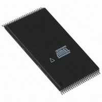
AT49BV6416-70TI SL383 Atmel, AT49BV6416-70TI SL383 Datasheet - Page 4

AT49BV6416-70TI SL383
Manufacturer Part Number
AT49BV6416-70TI SL383
Description
IC FLASH 64MBIT 70NS 48TSOP
Manufacturer
Atmel
Datasheet
1.AT49BV6416-70TU.pdf
(30 pages)
Specifications of AT49BV6416-70TI SL383
Format - Memory
FLASH
Memory Type
FLASH
Memory Size
64M (4M x 16)
Speed
70ns
Interface
Parallel
Voltage - Supply
2.7 V ~ 3.6 V
Operating Temperature
-40°C ~ 85°C
Package / Case
48-TSOP
Lead Free Status / RoHS Status
Contains lead / RoHS non-compliant
3.5.2
3.5.3
3.6
3.7
3.7.1
3.7.2
4
Word Programming
Flexible Sector Protection
AT49BV6416(T)
Plane Erase
Sector Erase
Softlock and Unlock
Hardlock and Write Protect (WP)
As a alternative to a full chip erase, the device is organized into four planes that can be individu-
ally erased. The plane erase command is a six-bus cycle operation. The plane whose address is
valid at the sixth falling edge of WE will be erased. The plane erase command does not alter the
data in protected sectors.
As an alternative to a full chip erase or a plane erase, the device is organized into multiple sec-
tors that can be individually erased. The Sector Erase command is a six-bus cycle operation.
The sector whose address is valid at the sixth falling edge of WE will be erased provided the
given sector has not been protected.
The device is programmed on a word-by-word basis. Programming is accomplished via the
internal device command register and is a four-bus cycle operation. The programming address
and data are latched in the fourth cycle. The device will automatically generate the required
internal programming pulses. Please note that a “0” cannot be programmed back to a “1”; only
erase operations can convert “0”s to “1”s.
The AT49BV6416(T) offers two sector protection modes, the Softlock and the Hardlock. The
Softlock mode is optimized as sector protection for sectors whose content changes frequently.
The Hardlock protection mode is recommended for sectors whose content changes infrequently.
Once either of these two modes is enabled, the contents of the selected sector is read-only and
cannot be erased or programmed. Each sector can be independently programmed for either the
Softlock or Hardlock sector protection mode. At power-up and reset, all sectors have their Soft-
lock protection mode enabled.
The Softlock protection mode can be disabled by issuing a two-bus cycle Unlock command to
the selected sector. Once a sector is unlocked, its contents can be erased or programmed. To
enable the Softlock protection mode, a six-bus cycle Softlock command must be issued to the
selected sector.
The Hardlock sector protection mode operates in conjunction with the Write Protection (WP) pin.
The Hardlock sector protection mode can be enabled by issuing a six-bus cycle Hardlock soft-
ware command to the selected sector. The state of the Write Protect pin affects whether the
Hardlock protection mode can be overridden.
To disable the Hardlock sector protection mode, the chip must be either reset or power cycled.
• When the WP pin is low and the Hardlock protection mode is enabled, the sector cannot be
• When the WP pin is high, the Hardlock protection mode is overridden and the sector can be
unlocked and the contents of the sector is read-only.
unlocked via the Unlock command.
3451D–FLASH–04/06


