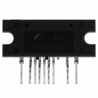
FSFA2100 Fairchild Semiconductor, FSFA2100 Datasheet - Page 10

FSFA2100
Manufacturer Part Number
FSFA2100
Description
IC SWIT OVP UVLO 9SIP
Manufacturer
Fairchild Semiconductor
Datasheet
1.FSFA2100.pdf
(16 pages)
Specifications of FSFA2100
Output Isolation
Isolated
Frequency Range
94 ~ 106kHz
Voltage - Input
14.5 ~ 25 V
Voltage - Output
650V
Power (watts)
200W
Operating Temperature
-40°C ~ 130°C
Package / Case
9-SIP
Output Voltage
25 V
Output Current
8 A
Output Power
450 W
Switching Frequency
300 KHz
Operating Temperature Range
- 40 C to + 130 C
Mounting Style
Through Hole
Duty Cycle (max)
55 %
Lead Free Status / RoHS Status
Lead free / RoHS Compliant
Available stocks
Company
Part Number
Manufacturer
Quantity
Price
© 2008 Fairchild Semiconductor Corporation
FSFA2100 • Rev. 1.0.0
Functional Description
1. Internal Oscillator: FSFA2100 employs a current-
controlled oscillator as shown in Figure 17. Internally, the
voltage of the R
charging/discharging current for the oscillator capacitor
C
(I
a resistor R
2. PWM Control: Figure 18 shows the typical control
circuit configuration. The opto-coupler transistor should
be connected to the V
capacitor to control the duty cycle.
Figure 19 shows the internal block diagram for PWM
operation. Duty cycle is controlled by comparing the
feedback voltage to the triangular signal with a range
from 1V to 3V.
CTC
f
T
S
is determined by the current flowing out of the R
=
). When the R
R
27
SET
Figure 17. Current Controlled Oscillator
k
Figure 18. PWM Control Configuration
Ω
×
SET
100
, the switching frequency is fixed as:
(
kHz
T
)
T
pin is pulled down to the ground with
pin is regulated at 2V and the
FB
pin in parallel with the feedback
T
(1)
pin
10
3. Protection Circuits: The FSFA2100 has Overload
Protection
(AOCP), Over-Voltage Protection (OVP), and Thermal
Shutdown (TSD) self-protective functions. The OLP and
OVP are auto-restart mode protections, while the AOCP and
TSD are latch-mode protections, as shown in Figure 20.
Auto-restart mode protection: Once the fault condition is
detected, the switching is terminated and the MOSFETs
remain off. When LV
around 11V, the protection is reset. The FPS resumes
normal operation when LV
about 14V.
Latch-mode protection: Once this protection is triggered,
the switching is terminated and the MOSFETs remain
off. The latch is reset only when LV
below 5V.
Low-side MOSFET current should be sensed for Pulse-
by-pulse current limit and AOCP. The FSFA2100 senses
drain current as a negative voltage, as shown in Figure
21 and Figure 22. Half-wave sensing allows low-power
dissipation in the sensing resistor, while full-wave
sensing has less noise in the sensing signal.
Figure 19. Internal PWM Block Diagram
(OLP),
Figure 20. Protection blocks
CC
Abnormal
falls down to LV
CC
reaches the start voltage of
Over-Current
CC
CC
stop voltage of
is discharged
www.fairchildsemi.com
Protection


