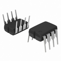
NCP1203P60G ON Semiconductor, NCP1203P60G Datasheet - Page 7

NCP1203P60G
Manufacturer Part Number
NCP1203P60G
Description
IC CTRLR PWM CM UVLO HV 8DIP
Manufacturer
ON Semiconductor
Datasheet
1.NCP1203P100G.pdf
(15 pages)
Specifications of NCP1203P60G
Output Isolation
Isolated
Frequency Range
57 ~ 73kHz
Voltage - Input
8.4 ~ 16 V
Voltage - Output
500V
Operating Temperature
-40°C ~ 150°C
Package / Case
8-DIP (0.300", 7.62mm)
Number Of Outputs
1
Duty Cycle (max)
80 % (Typ)
Output Current
250 mA
Mounting Style
Through Hole
Switching Frequency
65 KHz (Typ)
Operating Supply Voltage
16 V
Maximum Operating Temperature
125 C
Fall Time
28 ns
Minimum Operating Temperature
- 40 C
Rise Time
67 ns
Synchronous Pin
No
Topology
Flyback
Lead Free Status / RoHS Status
Lead free / RoHS Compliant
Other names
NCP1203P60GOS
Available stocks
Company
Part Number
Manufacturer
Quantity
Price
Company:
Part Number:
NCP1203P60G
Manufacturer:
ON Semiconductor
Quantity:
8 500
Part Number:
NCP1203P60G
Manufacturer:
ON/安森美
Quantity:
20 000
Introduction
architecture where the switch- -off time is dictated by the
peak current setpoint. This component represents the ideal
candidate where low part- -count is the key parameter,
particularly in low- -cost AC- -DC adapters, auxiliary
supplies etc. Due to its high- -performance SMARTMOS
High- -Voltage technology, the NCP1203 incorporates all the
necessary components normally needed in UC384X based
supplies: timing components, feedback devices, low- -pass
filter and startup device. This later point emphasizes the fact
that ON Semiconductor’s NCP1203 does not need an
external startup resistance but supplies the startup current
directly from the high- -voltage rail. On the other hand, more
and more applications are requiring low no- -load standby
power, e.g. for AC- -DC adapters, VCRs etc. UC384X series
have a lot of difficulty to reduce the switching losses at low
power levels. NCP1203 elegantly solves this problem by
constrained below 16 V, which is the maximum rating on
pin 6. Figure 14 portrays a typical startup sequence with a
V
CC
The NCP1203 implements a standard current mode
Once the power supply has started, the V
regulated at 12.5 V:
12.8 V/4.9 V
Figure 13. The Current Source Brings V
+
--
APPLICATION INFORMATION
CC
shall be
http://onsemi.com
6 mA or 0
7
CC
skipping unwanted switching cycles at a user- -adjustable
power level. By ensuring that skip cycles take place at low
peak current, the device ensures quiet, noise free operation.
Finally, an auto- -recovery output short- -circuit protection
(OCP) prevents from any lethal thermal runaway in
overload conditions.
Startup Sequence
outlet, the internal current source (typically 6.0 mA) is
biased and charges up the V
on this V
12.8 V), the current source turns off and no longer wastes
any power. At this time, the V
controller and the auxiliary supply is supposed to take over
before V
internal arrangement of this structure:
8
6
4
13.5
12.5
10.5
When the power supply is first powered from the mains
Above 12.8 V and then Turns Off
11.5
9.5
Figure 14. A Typical Startup Sequence for
CC
3.00 M
CC
CV
collapses below V
capacitor reaches the V
CC
12.8 V
8.00 M
HV
the NCP1203
Aux
t, TIME (sec)
CC
CC
13.0 M
CC(min)
capacitor. When the voltage
capacitor only supplies the
CC(on)
. Figure 13 shows the
18.0 M
level (typically
REGULATION
23.0 M


