NCP1377PG ON Semiconductor, NCP1377PG Datasheet - Page 3
NCP1377PG
Manufacturer Part Number
NCP1377PG
Description
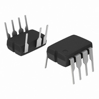
IC CTRLR PWM CM OVP UVLO 8DIP
Manufacturer
ON Semiconductor
Datasheet
1.NCP1377BPG.pdf
(17 pages)
Specifications of NCP1377PG
Output Isolation
Isolated
Frequency Range
100kHz
Voltage - Input
8.2 ~ 18 V
Operating Temperature
0°C ~ 125°C
Package / Case
8-DIP (0.300", 7.62mm), 7 Leads
Number Of Outputs
1
Output Voltage
18 V
Output Current
500 mA
Mounting Style
Through Hole
Switching Frequency
100 KHz
Maximum Operating Temperature
+ 150 C
Fall Time
20 ns
Rise Time
40 ns
Synchronous Pin
No
Topology
Flyback
Lead Free Status / RoHS Status
Lead free / RoHS Compliant
Other names
NCP1377PGOS
Available stocks
Company
Part Number
Manufacturer
Quantity
Price

Part Number:
NCP1377PG
Manufacturer:
ON/安森美
Quantity:
20 000


Stresses exceeding Maximum Ratings may damage the device. Maximum Ratings are stress ratings only. Functional operation above the
Recommended Operating Conditions is not implied. Extended exposure to stresses above the Recommended Operating Conditions may affect
device reliability.
V
MAXIMUM RATINGS
Continuous Power Supply or Drive Voltage
Transient Power Supply Voltage, Duration < 10 ms, I
Maximum Voltage on all other pins except Pin 8 (HV), Pin 6 (V
Maximum Current into all pins except V
odes are activated
Maximum Current in Pin 1
Thermal Resistance, Junction−to−Case
Thermal Resistance, Junction−to−Air, SOIC Version
Thermal Resistance, Junction−to−Air, PDIP Version
Maximum Junction Temperature
Temperature Shutdown
Hysteresis in Shutdown
Storage Temperature Range
ESD Capability, HBM Model (All pins except V
ESD Capability, Machine Model
Maximum Voltage on Pin 8 (HV), Pin 6 (V
HV
GND
CC
4 mA
To Internal
Supply
+
12.5 V
7.5 V
5.6 V (Fault)
+
PON
Mngt.
Fault
CC
5 V
CC
Rating
(6), HV (8) and Demag (1) when 10 V ESD di-
OVP
+
) Decoupled to Ground with 10 mF
CC
Figure 2. Internal Circuit Architecture
/1.44
and HV)
+
VCC
Demag
< 20 mA
http://onsemi.com
CC
Overload?
Timeout
) and Pin 5 (Drv)
5 us
3
Blanking
S
S
R R
8 us
4.5 us
Delay
Reset
Time
Q
Q
3 us for
B Version
1.5 us for B Version
-
+
+
V
V
Symbol
CC
TJ
CC
Idem
R
R
R
V
qJC
qJA
qJA
−
−
MAX
−
−
−
−
−
Pulse
HV
, Drv
V
+
50 mV
CC
Driver src = 20 sink = 10
Demag
1 V
−60 to +150
when DRV
380 ns
10 V
−0.3 to 10
+3.0/−2.0
LEB
Value
178
100
150
155
200
500
200 mA
is OFF
5.0
2.0
18
25
57
30
/3
Rint
4.2 V
Demag
°C/W
°C/W
°C/W
Unit
mA
mA
Drv
°C
°C
°C
°C
kV
FB
CS
V
V
V
V
V
Related parts for NCP1377PG
Image
Part Number
Description
Manufacturer
Datasheet
Request
R

Part Number:
Description:
ON Semiconductor [VOLTAGE REGULATOR]
Manufacturer:
ON Semiconductor
Datasheet:
Part Number:
Description:
357-036-542-201 CARDEDGE 36POS DL .156 BLK LOPRO
Manufacturer:
ON Semiconductor
Datasheet:
Part Number:
Description:
357-036-542-201 CARDEDGE 36POS DL .156 BLK LOPRO
Manufacturer:
ON Semiconductor
Datasheet:
Part Number:
Description:
357-036-542-201 CARDEDGE 36POS DL .156 BLK LOPRO
Manufacturer:
ON Semiconductor
Datasheet:
Part Number:
Description:
357-036-542-201 CARDEDGE 36POS DL .156 BLK LOPRO
Manufacturer:
ON Semiconductor
Datasheet:
Part Number:
Description:
357-036-542-201 CARDEDGE 36POS DL .156 BLK LOPRO
Manufacturer:
ON Semiconductor
Datasheet:
Part Number:
Description:
357-036-542-201 CARDEDGE 36POS DL .156 BLK LOPRO
Manufacturer:
ON Semiconductor
Datasheet:
Part Number:
Description:
357-036-542-201 CARDEDGE 36POS DL .156 BLK LOPRO
Manufacturer:
ON Semiconductor
Datasheet:
Part Number:
Description:
357-036-542-201 CARDEDGE 36POS DL .156 BLK LOPRO
Manufacturer:
ON Semiconductor
Datasheet:
Part Number:
Description:
357-036-542-201 CARDEDGE 36POS DL .156 BLK LOPRO
Manufacturer:
ON Semiconductor
Datasheet:
Part Number:
Description:
357-036-542-201 CARDEDGE 36POS DL .156 BLK LOPRO
Manufacturer:
ON Semiconductor
Datasheet:
Part Number:
Description:
Manufacturer:
ON Semiconductor
Datasheet:
Part Number:
Description:
Manufacturer:
ON Semiconductor
Datasheet:
Part Number:
Description:
Manufacturer:
ON Semiconductor
Datasheet: