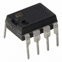
L6590AN STMicroelectronics, L6590AN Datasheet

L6590AN
Specifications of L6590AN
Available stocks
Related parts for L6590AN
L6590AN Summary of contents
Page 1
... FAX, TV, LASER PRINTER TYPICAL APPLICATION CIRCUIT AC line 88 to 264 Vac October 2000 FULLY INTEGRATED POWER SUPPLY ORDERING NUMBER: L6590AN - HOME APPLIANCES/LIGHTING LINE CARD, DC-DC CONVERTERS DESCRIPTION The L6590A is a monolithic switching regulator de- signed in BCD OFF-LINE technology, able to operate with wide range input voltage and to deliver up to 15W output power ...
Page 2
L6590A DESCRIPTION (continued) The MOSFET is source-grounded, thus it is possible to build flyback, boost and forward converters. The device is meant to work with secondary feed- back for tight tolerance of the regulated output volt- age. The internal fixed ...
Page 3
PIN FUNCTIONS N° Pin 1 DRAIN Drain connection of the internal power MOSFET. The internal high voltage start-up generator sinks current from this pin. 2 N.C. Not internally connected. Provision for clearance on the PCB. 3 Vcc Supply pin of ...
Page 4
L6590A ELECTRICAL CHARACTERISTCS (T Symbol Parameter POWER SECTION V Drain Source Voltage (BR)DSS I Off state drain current dss R Drain-to-Source on resistance DS(on see fig. 17 DS(on) j PWM CONTROL INPUT V Vout High COMPH ...
Page 5
ELECTRICAL CHARACTERISTICS (continued) Symbol Parameter I Peak switch current for Standby pksb Operation I Peak switch current for Normal pkno Operation BROWNOUT PROTECTION V Threshold Voltage th I Current Hysteresis Hys V Clamp Voltage CL THERMAL SHUTDOWN (***) Threshold Hysteresis ...
Page 6
L6590A Figure 1. Start-up & UVLO Thresholds Vcc [ - [°C] Figure 2. Start-up Current Generator Icc [mA] 5.5 Vdrain = 4.5 4 3.5 ...
Page 7
Figure 7. IC Operating Current Icc [mA] 4.4 MOSFET switching @ 22 kHz 4.2 4 3.8 3.6 3.4 3 Vcc [V] Figure 8. Switching Frequency vs. Temperature fsw [kHz] 80 Normal operation 70 ...
Page 8
L6590A Figure 13. COMP pin Characteristic VCOMP [ 0.2 0.4 0.6 0.8 ICOMP [mA] Figure 14. COMP pin Dynamic Resistance vs. Temperature RCOMP [kOhm] 10.5 10 9.5 9 8.5 8 -50 0 ...
Page 9
Figure 19. Coss vs. Drain Voltage Coss [pF] 250 °C 200 150 100 100 200 300 400 Vdrain [V] Figure 21. Test Board electrical schematic F1 2A/250V 100 nF ...
Page 10
L6590A Figure 22. Test Board evaluation data Test board Load & Line regulation Output Voltage [V] 5 4.98 4.96 4.94 4.92 4.9 0.003 0.01 0.03 0.1 Load Current [A] Test Board Light-load Consumption Input Power [mW] 1,200 1,000 800 600 ...
Page 11
Figure 24. Test Board main waveforms A1: Idrain Ch1: Vdrain A1: Idrain Ch1: Vdrain Figure 25. Test Board load transient response Vout Iout Standby Function is not tripped Ch1: Vdrain Vin = 100 V DC Iout = 2 A A1: ...
Page 12
L6590A APPLICATION INFORMATION In the following sections the functional blocks as well as the most important internal functions of the device will be described. Start-up circuit When power is first applied to the circuit and the voltage on the bulk ...
Page 13
Figure 27. PWM Control internal schematic OSCILLATOR Oscillator and PWM Control PWM regulation is accomplished by implementing voltage mode control. As shown in fig. 27, this block includes an oscillator, a PWM comparator, a PWM latch and a PWM control ...
Page 14
L6590A Figure 28. Standby Function timing diagram STANDBY (before filter) STANDBY (filtered) Brownout Protection Brownout Protection is basically a not-latched device shutdown functionality. It will typically be used to detect a mains undervoltage (brownout). This condition may cause overheating of ...
Page 15
Another problem is the spurious restarts that are likely to occur during converter power down if the input voltage decays slowly (e.g. with a large input bulk capacitor) and that cause the output voltage not to decay to zero monothonically. ...
Page 16
L6590A At turn-on, there are large current spikes due to the discharge of parasitic capacitances and, in case of Contin- uos Conduction Mode operation, to secondary diode reverse recovery as well, which could falsely trigger the OCP comparator. To increase ...
Page 17
APPLICATION IDEAS Figure 32. 15W Auxiliary SMPS for PC Vin = 200 to 375 Vdc R2 1 specification Core E20/10/6, ferrite 3C85 or N67 or equivalent 0.9 mm gap for a ...
Page 18
L6590A 18/19 ...
Page 19
... No license is granted by implication or otherwise under any patent or patent rights of STMicroelectronics. Specifications mentioned in this publication are subject to change without notice. This publication supersedes and replaces all information previously supplied. STMicroelectronics products are not authorized for use as critical components in life support devices or systems without express written approval of STMicroelectronics ...


