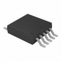
MCP73833-FCI/UN Microchip Technology, MCP73833-FCI/UN Datasheet - Page 21

MCP73833-FCI/UN
Manufacturer Part Number
MCP73833-FCI/UN
Description
IC LI-ION/LI-POLY CTRLR 10MSOP
Manufacturer
Microchip Technology
Specifications of MCP73833-FCI/UN
Battery Type
Lithium-Ion (Li-Ion), Lithium-Polymer (Li-Pol)
Function
Charge Management
Voltage - Supply
3.75 V ~ 6 V
Operating Temperature
-40°C ~ 85°C
Mounting Type
Surface Mount
Package / Case
10-TFSOP (0.118", 3.00mm Width)
Input Voltage
6V
Battery Charge Voltage
4.2V
Charge Current Max
1A
Battery Ic Case Style
MSOP
No. Of Pins
10
No. Of Series Cells
1
Output Voltage
4.2 V, 4.35 V, 4.4 V, 4.5 V
Output Current
1200 mA
Operating Supply Voltage
3.75 V to 6 V
Maximum Operating Temperature
+ 85 C
Minimum Operating Temperature
- 40 C
Mounting Style
SMD/SMT
Lead Free Status / RoHS Status
Lead free / RoHS Compliant
For Use With
MCP73833EV - BOARD EVAL FOR MCP73833
Lead Free Status / Rohs Status
Lead free / RoHS Compliant
Available stocks
Company
Part Number
Manufacturer
Quantity
Price
Company:
Part Number:
MCP73833-FCI/UN
Manufacturer:
Microchip Technology
Quantity:
135
Part Number:
MCP73833-FCI/UN
Manufacturer:
MICROCHIP/微芯
Quantity:
20 000
6.2
For optimum voltage regulation, place the battery pack
as close as possible to the device’s V
recommended to minimize voltage drops along the
high current-carrying PCB traces.
If the PCB layout is used as a heatsink, adding many
vias in the heatsink pad can help conduct more heat to
the backplane of the PCB, thus reducing the maximum
junction temperature. Figures
typical layout with PCB heatsinking.
FIGURE 6-4:
FIGURE 6-5:
© 2009 Microchip Technology Inc.
STAT1
STAT2
V
V
SS
DD
V
V
C
DD
SS
IN
PCB Layout Issues
MCP73833
Typical Layout (Top).
Typical Layout (Bottom).
R
PROG
6-4
and
BAT
and V
6-5
C
V
THERM
PG
depict a
BAT
OUT
V
SS
BAT
pins,
MCP73833/4
DS22005B-page 21


