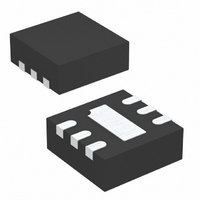
LTC4065EDC#TRMPBF Linear Technology, LTC4065EDC#TRMPBF Datasheet - Page 10

LTC4065EDC#TRMPBF
Manufacturer Part Number
LTC4065EDC#TRMPBF
Description
IC CHARGER BATT LI-ON 6-DFN
Manufacturer
Linear Technology
Datasheet
1.LTC4065EDCTRMPBF.pdf
(16 pages)
Specifications of LTC4065EDC#TRMPBF
Function
Charge Management
Battery Type
Lithium-Ion (Li-Ion)
Voltage - Supply
3.75 V ~ 5.5 V
Operating Temperature
-40°C ~ 85°C
Mounting Type
Surface Mount
Package / Case
6-WFDFN Exposed Pad
Output Current
500mA
Output Voltage
4.2V
Operating Supply Voltage (min)
3.75V
Operating Supply Voltage (max)
5.5V
Operating Temp Range
-40C to 85C
Mounting
Surface Mount
Pin Count
6
Operating Temperature Classification
Industrial
Lead Free Status / RoHS Status
Lead free / RoHS Compliant
Other names
LTC4065EDC#TRMPBFTR
Available stocks
Company
Part Number
Manufacturer
Quantity
Price
OPERATIO
LTC4065/LTC4065A
typical, not worst-case, ambient temperatures for a given
application with the assurance that the charger will auto-
matically reduce the current in worst-case conditions.
The charge cycle begins when the following conditions are
met: the voltage at the V
mately 80mV above the BAT pin voltage, a program
resistor is present from the PROG pin to ground and the EN
pin (LTC4065 only) is pulled below the shutdown thresh-
old (typically 0.82V).
If the BAT pin voltage is below 2.9V, the charger goes into
trickle charge mode, charging the battery at one-tenth the
programmed charge current to bring the cell voltage up to
a safe level for charging. If the BAT pin voltage is above
4.1V, the charger will not charge the battery as the cell is
near full capacity. Otherwise, the charger goes into the fast
charge constant-current mode.
When the BAT pin approaches the final float voltage
(4.2V), the LTC4065 enters constant-voltage mode and
the charge current begins to decrease. When the current
drops to 10% of the full-scale charge current, an internal
comparator turns off the N-channel MOSFET on the CHRG
pin and the pin assumes a high impedance state.
An internal timer sets the total charge time, t
cally 4.5 hours). When this time elapses, the charge cycle
terminates and the CHRG pin assumes a high impedance
state. To restart the charge cycle, remove the input voltage
and reapply it, momentarily force the EN pin above V
(typically 0.82V) for LTC4065, or momentarily float the
PROG pin and reconnect it (LTC4065A). The charge cycle
will automatically restart if the BAT pin voltage falls below
V
When the input voltage is not present, the battery drain
current is reduced to less than 4µA. The LTC4065 can also
be shut down by pulling the EN pin above the shutdown
threshold voltage. To put LTC4065A in shutdown mode,
float the PROG pin. This reduces input quiescent current
to less than 20µA and battery drain current to less than 1µA.
Programming Charge Current
The charge current is programmed using a single resistor
from the PROG pin to ground. The battery charge current
is 1000 times the current out of the PROG pin. The
10
RECHRG
(typically 4.1V).
U
CC
pin exceeds 3.6V and approxi-
TIMER
(typi-
MS
program resistor and the charge current are calculated
using the following equations:
The charge current out of the BAT pin can be determined
at any time by monitoring the PROG pin voltage and using
the following equation:
Undervoltage Lockout (UVLO)
An internal undervoltage lockout circuit monitors the input
voltage and keeps the charger in undervoltage lockout
until V
the BAT pin voltage. The 3.6V UVLO circuit has a built-in
hysteresis of approximately 0.6V and the automatic shut-
down threshold has a built-in hysteresis of approximately
50mV. During undervoltage lockout conditions, maxi-
mum battery drain current is 4µA and maximum supply
current is 11µA.
Shutdown Mode
The LTC4065 can be disabled by pulling the EN pin above
the shutdown threshold (approximately 0.82V). The
LTC4065A can be disabled by floating the PROG pin. In
shutdown mode, the battery drain current is reduced to
less than 1µA and the supply current to about 20µA.
Timer and Recharge
The LTC4065 has an internal termination timer that starts
when an input voltage greater than the undervoltage
lockout threshold is applied to V
shutdown the battery voltage is less than the recharge
threshold.
At power-up or when exiting shutdown, if the battery
voltage is less than the recharge threshold, the charge
time is set to 4.5 hours. If the battery voltage is greater than
the recharge threshold at power-up or when exiting shut-
down, the timer will not start and charging is prevented
since the battery is at or near full capacity.
I
R
BAT
PROG
CC
=
rises above 3.6V and approximately 80mV above
R
=
V
PROG
PROG
1000
• 1000
•
I
CHG
1
V
,
I
CHG
=
1000
R
PROG
CC
, or when leaving
V
4065fb


