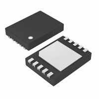
DS2781G+ Maxim Integrated Products, DS2781G+ Datasheet - Page 11

DS2781G+
Manufacturer Part Number
DS2781G+
Description
IC FUEL GAUGE STND ALONE 10-TDFN
Manufacturer
Maxim Integrated Products
Datasheet
1.DS2781E.pdf
(31 pages)
Specifications of DS2781G+
Function
Fuel, Gas Gauge/Monitor
Battery Type
Lithium-Ion (Li-Ion), Lithium-Polymer (Li-Pol)
Voltage - Supply
2.5 V ~ 10 V
Operating Temperature
-40°C ~ 85°C
Mounting Type
Surface Mount
Package / Case
10-TDFN Exposed Pad
Operating Supply Voltage
2.5 V to 10 V
Supply Current
70 uA
Maximum Operating Temperature
+ 85 C
Minimum Operating Temperature
- 40 C
Charge Safety Timers
No
Mounting Style
SMD/SMT
Temperature Monitoring
Yes
Lead Free Status / RoHS Status
Lead free / RoHS Compliant
ACCUMULATION BIAS
The Accumulation Bias register (AB) allows an arbitrary bias to be introduced into the current-accumulation
process. The AB can be used to account for currents that do not flow through the sense resistor, estimate currents
too small to measure, estimate battery self-discharge or correct for static offset of the individual DS2781 device.
The AB register allows a user programmed constant positive or negative polarity bias to be included in the current
accumulation process. The user-programmed two’s complement value, with bit weighting the same as the current
register, is added to the ACR once per current conversion cycle. The AB value is loaded on power-up from
EEPROM memory. The format of the AB register is shown in Figure 10.
Figure 10. Accumulation Bias Register Formats
CURRENT BLANKING
The Current Blanking feature modifies current measurement result prior to being accumulated in the ACR. Current
Blanking occurs conditionally when a current measurement (raw current + COB) falls in one of two defined ranges.
The first range prevents charge currents less than 100μV from being accumulated. The second range prevents
discharge currents less than 25μV in magnitude from being accumulated. Charge current blanking is always
performed, however, discharge current blanking must be enabled by setting the NBEN bit in the Control register.
See the register description for additional information.
CAPACITY ESTIMATION ALGORITHM
Remaining capacity estimation uses real-time measured values and stored parameters describing the cell stack
characteristics and application operating limits. The following diagram describes the algorithm inputs and outputs.
AB
“S”: sign bit
MSb
S
2
6
2
5
11 of 31
Address 61h
2
4
Units:
2
3
2
2
1.5625μV/Rsns
2
1
EE
LSb
2
0


