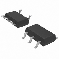
LTC4054LES5-4.2#TRM Linear Technology, LTC4054LES5-4.2#TRM Datasheet - Page 13

LTC4054LES5-4.2#TRM
Manufacturer Part Number
LTC4054LES5-4.2#TRM
Description
IC CHARGR BATTERY L-ION TSOT23-5
Manufacturer
Linear Technology
Datasheet
1.LTC4054LES5-4.2TRPBF.pdf
(16 pages)
Specifications of LTC4054LES5-4.2#TRM
Function
Charge Management
Battery Type
Lithium-Ion (Li-Ion)
Voltage - Supply
4.25 V ~ 6.5 V
Operating Temperature
-40°C ~ 85°C
Mounting Type
Surface Mount
Package / Case
SOT-23-5 Thin, TSOT-23-5
Lead Free Status / RoHS Status
Contains lead / RoHS non-compliant
Other names
LTC4054LES5-4.2
LTC4054LES5-4.2
LTC4054LES5-4.2
Available stocks
Company
Part Number
Manufacturer
Quantity
Price
Part Number:
LTC4054LES5-4.2#TRMLTC4054LES5-4.2#25221
Manufacturer:
LINEAR/凌特
Quantity:
20 000
APPLICATIO S I FOR ATIO
V
Many types of capacitors can be used for input bypassing,
however, caution must be exercised when using multi-
layer ceramic capacitors. Because of the self resonant and
high Q characteristics of some types of ceramic capaci-
tors, high voltage transients can be generated under some
start-up conditions, such as connecting the charger input
to a live power source. Adding a 1.5 resistor in series
with an X5R ceramic capacitor will minimize start-up
voltage transients. For more information, refer to Applica-
tion Note 88.
Charge Current Soft-Start
The LTC4054L includes a soft-start circuit to minimize the
inrush current at the start of a charge cycle. When a charge
cycle is initiated, the charge current ramps from zero to the
full-scale current over a period of approximately 100 s.
This has the effect of minimizing the transient current load
on the power supply during start-up.
CHRG Status Output Pin
The CHRG pin can provide an indication that the input
voltage is greater than the undervoltage lockout thresh-
old level. A weak pull-down current of approximately
20 A indicates that sufficient voltage is applied to V
begin charging. When a discharged battery is connected
to the charger, the constant current portion of the charge
CC
Bypass Capacitor
U
U
Figure 3. Using a Microprocessor to Determine CHRG State
W
LTC4054L
U
V
V
CC
+
CHRG
CC
to
800k
2k
cycle begins and the CHRG pin pulls to ground. The
CHRG pin can sink up to 10mA to drive an LED that
indicates that a charge cycle is in progress.
When the battery is nearing full charge, the charger enters
the constant-voltage portion of the charge cycle and the
charge current begins to drop. When the charge current
drops below 1/10 of the programmed current, the charge
cycle ends, and the strong pull-down is replaced by the
20 A pull-down, indicating that the charge cycle has
ended. If the input voltage is removed or drops below the
undervoltage lockout threshold, the CHRG pin becomes
high impedance. Figure 3 shows that by using two differ-
ent value pull-up resistors, a microprocessor can detect all
three states from this pin.
To detect when the LTC4054L is in charge mode, force the
digital output pin (OUT) high and measure the voltage at
the CHRG pin. The N-channel MOSFET will pull the pin
voltage low even with the 2k pull-up resistor. Once the
charge cycle terminates, the N-channel MOSFET is turned
off and a 20 A current source is connected to the CHRG
pin. The IN pin will then be pulled high by the 2k pull-up
resistor. To determine if there is a weak pull-down current,
the OUT pin should be forced to a high impedance state.
The weak current source will pull the IN pin low through
the 800k resistor; if CHRG is high impedance, the IN pin
will be pulled high, indicating that the part is in a UVLO
state.
OUT
IN
PROCESSOR
V
DD
4054L42 F03
LTC4054L-4.2
13
4054l42f


