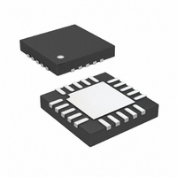
LTC4012CUF-3#PBF Linear Technology, LTC4012CUF-3#PBF Datasheet - Page 21

LTC4012CUF-3#PBF
Manufacturer Part Number
LTC4012CUF-3#PBF
Description
IC BATT CHRGR MC HI-EFF 20-QFN
Manufacturer
Linear Technology
Datasheet
1.LTC4012CUF-3PBF.pdf
(28 pages)
Specifications of LTC4012CUF-3#PBF
Function
Charge Management
Battery Type
Multi-Chemistry
Voltage - Supply
6 V ~ 28 V
Operating Temperature
0°C ~ 85°C
Mounting Type
Surface Mount
Package / Case
20-WFQFN Exposed Pad
Lead Free Status / RoHS Status
Lead free / RoHS Compliant
Available stocks
Company
Part Number
Manufacturer
Quantity
Price
applicaTions inForMaTion
The output capacitor shown across the battery and ground
must also absorb PWM output ripple current. The general
formula for this capacitor current is:
For example, I
High capacity ceramic capacitors (20µF or more) available
from a variety of manufacturers can be used for input/out-
put capacitors. Other alternatives include OS-CON and
POSCAP capacitors from Sanyo.
Low ESR solid tantalum capacitors have high ripple cur-
rent rating in a relatively small surface mount package,
but exercise caution when using tantalum for input or
output bulk capacitors. High input surge current can be
created when the adapter is hot-plugged to the charger
or when a battery is connected to the charger. Solid tan-
talum capacitors have a known failure mechanism when
subjected to very high surge currents. Select tantalum
capacitors that have high surge current ratings or have
been surge tested.
EMI considerations usually make it desirable to minimize
ripple current in battery leads. Adding Ferrite beads or
inductors can increase battery impedance at the nominal
550kHz switching frequency. Switching ripple current splits
between the battery and the output capacitor in inverse
relation to capacitor ESR and the battery impedance. If
the ESR of the output capacitor is 0.2Ω and the battery
impedance is raised to 4Ω with a ferrite bead, only 5%
of the current ripple will flow to the battery.
V
V
L1 = 10µH
f
I
PWM
RMS
BAT
CLP
= 12.6V
= 19V
= 550kHz
=
0 29
.
RMS
•
V
L
BAT
= 0.22A with:
1
•
f
•
PWM
1
–
V
V
CLP
BAT
Inductor Selection
Higher switching frequency generally results in lower ef-
ficiency because of MOSFET gate charge losses, but it allows
smaller inductor and capacitor values to be used. A primary
effect of the inductor value L1 is the amplitude of ripple
current created. The inductor ripple current ∆I
with higher inductance and PWM operating frequency:
Accepting larger values of ∆I
ductance, but results in higher output voltage ripple and
greater core losses. Lower charge currents generally call
for larger inductor values.
The LTC4012-3 limits maximum instantaneous peak in-
ductor current during every PWM cycle. To avoid unstable
switch waveforms, the ripple current must satisfy:
so choose:
For C-grade parts, a reasonable starting point for setting
ripple current is ∆I
∆I
batteries over the wider I-grade temperature range. The
voltage compliance of internal LTC4012-3 circuits also
imposes limits on ripple current. Select R
to avoid average current errors in high ripple designs. The
following equation can be used for guidance:
L
L
∆I
∆I
R
= 0.2 • I
1
SENSE
L
L
>
50
=
<
f
PWM
2
V
µA
BAT
•
MAX
•
∆
L
R
150
0 125
•
I
1
• –
L
SENSE
.
only if the IC will actually be used to charge
•
R
150
1
≤
mV
f
SENSE
PWM
R
L
•
mV
IN
V
V
= 0.4 • I
–
V
BAT
CLP
CLP
≤
I
MAX
–
R
I
SENSE
MAX
20
MAX
L
allows the use of low in-
µA
. For I-grade parts, use
•
∆
LTC4012-3
I
L
IN
(in Figure 1)
L
decreases
40123fb


