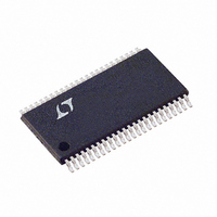
LTC1760CFW Linear Technology, LTC1760CFW Datasheet - Page 36

LTC1760CFW
Manufacturer Part Number
LTC1760CFW
Description
IC MANAGER BATTERY DUAL 48TSSOP
Manufacturer
Linear Technology
Datasheet
1.LTC1760CFWPBF.pdf
(44 pages)
Specifications of LTC1760CFW
Function
Charge Management
Battery Type
Smart Batteries
Voltage - Supply
6 V ~ 28 V
Operating Temperature
0°C ~ 70°C
Mounting Type
Surface Mount
Package / Case
48-TFSOP (0.240", 6.10mm Width)
Lead Free Status / RoHS Status
Contains lead / RoHS non-compliant
Available stocks
Company
Part Number
Manufacturer
Quantity
Price
Company:
Part Number:
LTC1760CFW
Manufacturer:
Linear Technology
Quantity:
1 855
Company:
Part Number:
LTC1760CFW
Manufacturer:
ST
Quantity:
215
Part Number:
LTC1760CFW
Manufacturer:
LT/凌特
Quantity:
20 000
Company:
Part Number:
LTC1760CFW#PBF
Manufacturer:
LT
Quantity:
2
Part Number:
LTC1760CFW#PBF
Manufacturer:
LINEAR/凌特
Quantity:
20 000
LTC1760
APPLICATIO S I FOR ATIO
Sample calculation of I
Sample calculation of I
(R
SMBus Host communication:
36
Thermistor Impedance
THX
For thermistors that are IDEAL-RANGE:
I
(R1A +R
For thermistors that are HOT-RANGE:
I
(R1A +R
R
ground.
RXB = 54.9k
RXA = 1.13k
I
I
R
and I
R
R
GND.
R
GND.
I
SMBus Host and depends on the amount of bus
traffic.
I
with Battery1 or Battery2.
I
I
SAFETYX
SAFETYX
VLIM
ILIM
SMB
SMB_BATX
SMB_BATX
SMBALERT
THX
LIM_PU
LIM_PU
VLIMIT
ILIMIT
= 400), R
R
= V
LIMIT.
is the current used for communicating with the
is the impedance of the battery’s thermistor to
THX
= V
100k
3.3k
400
is the value of the resistance from I
is the value of the resistance from V
VCC2
THX
THX
= 4/64 • V
= 4/64 • V
(Ω)
is the typical pull-up impedance at V
= 34k.
VCC2
is the current used for communicating
= 350µA • 0.0155 = 5.425µA.
is defined in “Electrical Characteristics.”
)
)
VLIMIT
/(R
/(R
ILIMIT
VLIMIT
U
VCC2
= R
VCC2
DCIN_CHG
SAFETYX
Thermistor Range
+ R
UNDER_RANGE
ILIMIT
IDEAL_RANGE
OVER_RANGE
U
+ R
/(RXB + R
/(RXB + R
LIM_PU
LIM_PU
= 30k, V
with V
with two Li-Ion batteries
).
W
).
THX
THX
VCC2
CC2
) + 4/64 • V
) + 2/64 • V
= 5.2V
= 5.2V, and no
I
SAFETYX
LIMIT
U
1.05
42.2
218
LIMIT
LIMIT
(µA)
VCC2
to
VCC2
to
/
/
The total operating current through BAT1 and BAT2 when
AC is not present (I
where:
Sample calculation of I
Sample calculation with two Li-Ion batteries (R
400), V
Thermistor Impedance
I
I
I
= 1.3mA + 700µA + 218µA + 218µA +81µA + 81µA
+ 0µA + 5.4µA + 5.4µA + 0µA = 2.62mA
I
I
I
I
I
thermistor connected to SAFETY1 or SAFETY2.
I
R
ground.
RXB = 54.9k.
I
ing with Battery1 or Battery2 when AC in not present.
I
I
SMBus Host and depends on the amount of bus
traffic.
I
I
= 175µA + 80µA + 2.9µA + 2.9µA + 0µA + 2.4µA +
2.4µA + 0µA = 265µA
DCIN_CHG
VLIM
SMBALERT
BAT_NOAC
SMB
BAT
VCC2_AC0
SAFETYX
SAFETYX
SMB_BATX_ACO
SMB_BATX_AC0
SMB
BAT_NOAC
SMB
THX
R
is defined in “Electrical Characteristics.”
CC2
+ I
is the current used for communicating with the
+ I
+ I
is the impedance of the battery’s thermistor to
THX
400
SMB_BAT1_AC0
SMB_BAT1_AC0
ILIM
= 5.2V, and no SMBus Host communication:
is the current used to test the battery
= 2/64 • V
(Ω)
is defined in “Electrical Characteristics.”
= I
– I
= I
+ I
CH1
BAT
BAT
= 350µA • 0.00687 = 2.404µA.
is the current used for communicat-
SMB
BAT_NOAC
+ I
+ I
+ I
VCC2
VCC2_AC1
VCC2_AC0
VCC2_AC0
+ I
SAFETY
Thermistor Range
+ I
+ I
UNDER_RANGE
SMB_BAT1
/(RXB + R
SMB_BAT2_AC0
SMB_BAT2_AC0
) is given by:
with V
+ I
+ I
+ I
SAFETY1
SAFETY1
SAFETY1
+ I
THX
VCC2
SMB_BAT2
).
= 5.2V
+ I
+ I
+ I
+ I
+ I
I
SAFETYX
SMBALERT
SMBALERT
SAFETY2
SAFETY2
SAFETY2
2.9
THX
+
(µA)
=
+
+
+
1760f


