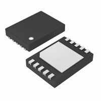
DS2782G-5+T&R Maxim Integrated Products, DS2782G-5+T&R Datasheet - Page 7

DS2782G-5+T&R
Manufacturer Part Number
DS2782G-5+T&R
Description
IC FUEL GAUGE STND-ALONE 10-TDFN
Manufacturer
Maxim Integrated Products
Datasheet
1.DS2782E.pdf
(28 pages)
Specifications of DS2782G-5+T&R
Function
Fuel, Gas Gauge/Monitor
Battery Type
Lithium-Ion (Li-Ion), Lithium-Polymer (Li-Pol)
Voltage - Supply
2.5 V ~ 5.5 V
Operating Temperature
-40°C ~ 85°C
Mounting Type
Surface Mount
Package / Case
10-TDFN Exposed Pad
Lead Free Status / RoHS Status
Lead free / RoHS Compliant
POWER MODES
The DS2782 has two power modes: ACTIVE and SLEEP. On initial power up, the DS2782 defaults to ACTIVE
mode. While in ACTIVE mode, the DS2782 is fully functional with measurements and capacity estimation
continuously updated. In SLEEP mode, the DS2782 conserves power by disabling measurement and capacity
estimation functions, but preserves register contents. SLEEP mode is entered under two different conditions and
an enable bit for each condition makes entry into SLEEP optional. SLEEP mode can be enabled using the Power
Mode (PMOD) bit or the Under Voltage Enable (UVEN) bit.
The PMOD type SLEEP is entered if the PMOD bit is set AND a bus low condition occurs. A bus low condition,
where both SDA AND SCL low for t
in which the bus pull-up voltage, V
current will flow and therefore coulomb counting is not necessary. A system with PMOD SLEEP enabled must
ensure that a stand-alone or cradle charger includes a pull-up on SDA and/or SCL. The DS2782 transitions from
PMOD SLEEP to ACTIVE mode when either SDA or SCL is pulled high.
The second option for entering SLEEP is an under voltage condition measured on VIN. When the UVEN bit is set,
the DS2782 will transition to SLEEP if the voltage on VIN is less than V
is in a bus high or a bus low condition for t
communication resumes to prevent over discharging the battery. The DS2782 transitions from UVEN SLEEP to
ACTIVE mode when either SDA or SCL change logic state. The bus master should initiate a transaction after
charging of a depleted battery begins.
Note: PMOD and UVEN SLEEP features must be disabled when a battery is charged on an external charger that
does not connect to SDA and/or SCL. PMOD SLEEP can be used if the charger pulls the bus high. The DS2782
remains in SLEEP and therefore does not measure or accumulate current when a battery is charged on a charger
that fails to properly drive the communication bus.
INITIATING COMMUNICATION IN SLEEP
When beginning communication with a DS2782 in PMOD SLEEP, the bus must be pulled up before a START bit
can be issued by the master. In UVEN SLEEP, the procedure depends on the bus state when UVEN SLEEP was
entered. If the bus was low, it must be pulled up before a START bit can be issued by the master as required with
PMOD SLEEP. If the bus was high when UVEN SLEEP was entered, then the DS2782 is prepared to receive a
START bit from the master. A standard procedure of issuing a START – STOP – START when the host system is
powered up on the charger input properly initiates communication from both PMOD and UVEN SLEEP modes.
VOLTAGE MEASUREMENT
Battery voltage is measured at the VIN input with respect to VSS over a range of 0V to 4.5V, with a resolution of
4.88mV. The result is updated every 440ms and placed in the VOLTAGE register in two’s complement form.
Voltages above the maximum register value are reported at the maximum value; voltages below the minimum
register value are reported at the minimum value. The format of the voltage register is shown in Figure 4.
Figure 4. Voltage Register Format
VOLT
MSb
“S”: sign bit(s), “X”: reserved
S
2
9
MSB—Address 0Ch
2
8
2
7
2
6
SLEEP
PULLUP
2
5
(2s nominal), is used to detect a pack disconnection or system shutdown
, is not present. PMOD SLEEP assumes that no charge or discharge
2
SLEEP
4
LSb
2
. UVEN SLEEP relieves the battery of the DS2782 load until
3
7 of 28
MSb
2
2
2
1
SLEEP
LSB—Address 0Dh
2
0
(2.45V nominal) AND the 2-Wire bus
X
X
X
Units: 4.88mV
Read Only
X
LSb
X


