MAX745EAP+ Maxim Integrated Products, MAX745EAP+ Datasheet
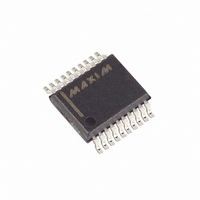
IC BATTERY CHARGER LI+ 20-SSOP

MAX745EAP+

Manufacturer Part Number
MAX745EAP+
Description
IC BATTERY CHARGER LI+ 20-SSOP
Manufacturer
Maxim Integrated Products
Datasheet

Specifications of MAX745EAP+

Function
Charge Management
Battery Type
Lithium-Ion (Li-Ion)
Voltage - Supply
6 V ~ 24 V
Operating Temperature
-40°C ~ 85°C
Mounting Type
Surface Mount
Package / Case
20-SSOP
Output Voltage
5.4 V
Operating Supply Voltage
6 V to 24 V
Supply Current
4 mA
Maximum Operating Temperature
+ 85 C
Minimum Operating Temperature
- 40 C
Mounting Style
SMD/SMT
Lead Free Status / RoHS Status
Lead free / RoHS Compliant
The MAX745 provides all functions necessary for
charging lithium-ion (Li+) battery packs. It provides a
regulated charging current of up to 4A without getting
hot, and a regulated voltage with only ±0.75% total
error at the battery terminals. It uses low-cost, 1% resis-
tors to set the output voltage, and a low-cost N-channel
MOSFET as the power switch.
The MAX745 regulates the voltage set point and charg-
ing current using two loops that work together to transi-
tion smoothly between voltage and current regulation.
The per-cell battery voltage regulation limit is set
between 4V and 4.4V using standard 1% resistors, and
then the number of cells is set from 1 to 4 by pin-strap-
ping. Total output voltage error is less than ±0.75%.
For a similar device with an SMBus™ microcontroller
interface and the ability to charge NiCd and NiMH cells,
refer to the MAX1647 and MAX1648. For a low-cost Li+
charger using a linear-regulator control scheme, refer
to the MAX846A.
________________________Applications
19-1182; Rev 3; 10/01
SMBus is a trademark of Intel Corp.
For pricing, delivery, and ordering information, please contact Maxim/Dallas Direct! at
1-888-629-4642, or visit Maxim’s website at www.maxim-ic.com.
Li+ Battery Packs
Desktop Cradle Chargers
Cellular Phones
Notebook Computers
Hand-Held Instruments
WITH 1% RESISTORS
CELL VOLTAGE
ON
________________________________________________________________ Maxim Integrated Products
SET PER
(UP TO 24V)
SELECT
COUNT
CELL
General Description
OFF
V
IN
STATUS
CELL0
CELL1
THM/SHDN
REF
SETI
VADJ
CCV
CCI
MAX745
DCIN
GND
IBAT
PGND
BATT
DLO
BST
DHI
CS
Switch-Mode Lithium-Ion
VL
LX
o Charges 1 to 4 Li+ Battery Cells
o ±0.75% Voltage-Regulation Accuracy
o Provides up to 4A without Excessive Heating
o 90% Efficient
o Uses Low-Cost Set Resistors and
o Up to 24V Input
o Up to 18V Maximum Battery Voltage
o 300kHz Pulse-Width Modulated (PWM) Operation
o Stand-Alone Operation—No Microcontroller
____________________________Features
*Dice are tested at T
Pin Configuration appears at end of data sheet.
MAX745C/D
MAX745EAP
N-Channel Switch
Needed
Using 1% Resistors
Low-Noise, Small Components
PART
N
N
Typical Operating Circuit
Battery-Charger
A
= +25°C.
TEMP RANGE
40°C to +85°C
0°C to +70°C
Ordering Information
R
SENSE
I
VOUT
1–4 Li+ CELLS
(UP TO 18V)
CHARGE
PIN-PACKAGE
Dice*
20 SSOP
1

Related parts for MAX745EAP+

MAX745EAP+ Summary of contents

Page 1

... ON OFF SET PER CELL VOLTAGE WITH 1% RESISTORS SMBus is a trademark of Intel Corp. ________________________________________________________________ Maxim Integrated Products For pricing, delivery, and ordering information, please contact Maxim/Dallas Direct! at 1-888-629-4642, or visit Maxim’s website at www.maxim-ic.com. Switch-Mode Lithium-Ion ____________________________Features o Charges Li+ Battery Cells o ±0.75% Voltage-Regulation Accuracy ...

Page 2

Switch-Mode Lithium-Ion Battery Charger ABSOLUTE MAXIMUM RATINGS DCIN to GND ............................................................-0.3V to 26V BST, DHI to GND ......................................................-0.3V to 30V BST to LX ....................................................................-0. DHI to LX............................................(LX - 0.3V) to (BST + 0.3V GND ................................................-0.3V to ...

Page 3

ELECTRICAL CHARACTERISTICS (continued 18V 8.4V 0°C to +85°C. Typical values are at T DCIN BATT A PARAMETER ERROR AMPLIFIERS GMV Amplifier Transconductance GMI Amplifier Transconductance GMV Amplifier Output Current GMI Amplifier Output Current CCI ...

Page 4

Switch-Mode Lithium-Ion Battery Charger __________________________________________Typical Operating Characteristics (T = +25° 18V 4.2V, CELL0 = CELL1 = GND DCIN BATT noted.) BATTERY VOLTAGE vs. CHARGING CURRENT 4.5 4.0 3.5 3.0 2.5 2.0 1.5 1.0 R1 ...

Page 5

Description PIN NAME Current-Sense Amplifier’s Analog Current-Source Output. See the Monitoring Charge Current section for a 1 IBAT detailed description. 2 DCIN Charger Input Voltage. Bypass DCIN with a 0.1µF capacitor Chip Power Supply. Output of the ...

Page 6

Switch-Mode Lithium-Ion Battery Charger the voltage limit is 4.2V. Table 1 defines the REF battery cell count. The battery limit voltage is set by the following:       ...

Page 7

To set currents below full scale without changing R1, adjust the voltage at SETI according to the follow- ing formula SETI CHG FS A capacitor at CCI sets the current-feedback loop’s dominant pole. While ...

Page 8

Switch-Mode Lithium-Ion Battery Charger MOSFET Drivers The MAX745 drives external N-channel MOSFETs to switch the input source generating the battery voltage or current. Since the high-side N-channel MOSFET’s gate must be driven to a voltage higher than the input source ...

Related keywords