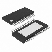
MAX7456EUI+ Maxim Integrated Products, MAX7456EUI+ Datasheet - Page 29

MAX7456EUI+
Manufacturer Part Number
MAX7456EUI+
Description
IC ON-SCREEN DISPLAY 28-TSSOP
Manufacturer
Maxim Integrated Products
Type
OSD (On-Screen Display) Video Generatorr
Datasheet
1.MAX7456EUI.pdf
(44 pages)
Specifications of MAX7456EUI+
Applications
Security Systems, Video Routing
Mounting Type
Surface Mount
Package / Case
28-TSSOP Exposed Pad, 28-eTSSOP, 28-HTSSOP
Current - Supply
58mA
Voltage - Supply
4.75 V ~ 5.25 V
Operating Temperature
-40°C ~ 85°C
Interface
SPI Serial
Display Type
OSD
Digits Or Characters
256 Characters
Maximum Clock Frequency
27 MHz
Operating Supply Voltage
5 V
Maximum Power Dissipation
2162 mW
Maximum Operating Temperature
+ 85 C
Maximum Supply Current
25 mA
Minimum Operating Temperature
- 40 C
Mounting Style
SMD/SMT
Lead Free Status / RoHS Status
Lead free / RoHS Compliant
Configuration
-
Lead Free Status / Rohs Status
Lead free / RoHS Compliant
BIT
2
1
0
DEFAULT
______________________________________________________________________________________
0
0
0
Single-Channel Monochrome On-Screen
Clear Display Memory
0 = Inactive
1 = Clear (fill all display memories with zeros)
Note: This bit is automatically cleared after the operation is completed (the operation requires
20µs). The user does not need to write a 0 afterwards. The status of the bit can be checked by
reading this register.
This operation is automatically performed:
Vertical Sync Clear
Valid only when clear display memory = 1, (DMM[2] = 1)
0 = Immediately applies the clear display-memory command, DMM[2] = 1
1 = Applies the clear display-memory command, DMM[2] = 1, at the next VSYNC time
Auto-Increment Mode
Auto-increment mode increases the speed at which the display memory can be written by
automatically incrementing the character address for each successive character written. This mode
reduces the number of SPI commands, and thus the time needed to write a string of adjacent
characters. This mode is useful when writing strings of characters written from left-to-right, top-to-
bottom, on the display (see Table 5).
0 = Disabled
1 = Enabled
When this bit is enabled for the first time, data in the Display Memory Address (DMAH[0] and
DMAL[7:0]) registers are used as the starting location to which the data is written. When performing
the auto-increment write for the display memory, the 8-bit address is internally generated, and
therefore only 8-bit data is required by the SPI-compatible interface (Figure 21). The content is to
be interpreted as a Character Address byte if DMAH[1] = 0 or a Character Attribute byte if
DMAH[1] = 1. This mode is disabled by writing the escape character 1111 1111.
If the Clear Display Memory bit is set, this bit is reset internally.
a) On power-up
b) Immediately following the rising edge of RESET
c) Immediately following the rising edge of CS after VM0[1] has been set to 1
Display with Integrated EEPROM
Display Memory Mode Register (DMM) (continued)
FUNCTION
29


