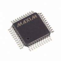
MAX6960AMH+D Maxim Integrated Products, MAX6960AMH+D Datasheet - Page 31

MAX6960AMH+D
Manufacturer Part Number
MAX6960AMH+D
Description
IC DRVR LED 8X8 44-MQFP
Manufacturer
Maxim Integrated Products
Datasheet
1.MAX6963ATH.pdf
(35 pages)
Specifications of MAX6960AMH+D
Display Type
LED
Configuration
8 x 8 (Matrix)
Interface
4-Wire Serial
Digits Or Characters
Any Digit Type
Current - Supply
7.5mA
Voltage - Supply
2.7 V ~ 3.6 V
Operating Temperature
-40°C ~ 125°C
Mounting Type
Surface Mount
Package / Case
44-MQFP, 44-PQFP
Number Of Segments
64
Low Level Output Current
750000 uA
High Level Output Current
48000 uA
Operating Supply Voltage
2.7 V to 3.6 V
Maximum Supply Current
11 mA
Maximum Power Dissipation
1012 mW
Maximum Operating Temperature
+ 125 C
Mounting Style
SMD/SMT
Minimum Operating Temperature
- 40 C
Lead Free Status / RoHS Status
Lead free / RoHS Compliant
To use these drivers, choose R1 to set the desired
peak segment current I
supply voltage V
drop V
Choose R2 to pass 5mA in order to drop 5V across R3
to provide 5V gate drive to logic-level pFET Q2:
Rate Q1 at segment current I
current, which is 16 times I
A MAX6960 can drive an 8 x 16 LED matrix, and so one
MAX6960 can drive two 8 x 8 monocolor digits or one 8
x 8 RGY digit. A MAX6960 cannot directly drive an 8 x
8 RGB display digit, but MAX6960s can nevertheless
be used to build RGB panels.
The MAX6960 drivers provide 3 x 2 = 6 bits of color
control to an RGB panel, or 64 colors.
The best way to drive RGB LEDs with the MAX6960 is to
use three 3-wire buses, one for each color (Figure 17). A
single 4-wire interface must be used, with three CSs,
Figure 16. Current and Voltage Boosting MAX6960–MAX6963
with External Transistors
Using the MAX6960 as Driver/Controller
LED
I
R2 = (V
PEAK
ROW1–ROW8
COL1–COL16
:
= (V
DRIVER
47kΩ
DRIVER
(R1 + R
R4
______________________________________________________________________________________
DRIVER
V+
820Ω
R5
- V
Q3
PEAK
820Ω
and the LED forward voltage
DS(ON)Q2
CE(SAT)Q3
- V
1kΩ
PEAK
R3
R2
R6
V
LED
DRIVER
OV
0V
PEAK
according to the driver
.
CATHODE COLUMN DRIVE
Q1
- V
for RGB Displays
ANODE ROW DRIVE
) A
, and rate Q2 at row
G
CE(SAT)Q1
- 5) x 200Ω
8 x 8 Matrix Graphic LED Drivers
(1 OF 16)
V
(1 OF 8)
DRIVER
0V
S
Q2
D
R1
) /
4-Wire Serially Interfaced
again one for each color. The red and green LEDs are
driven directly by their MAX6960s, and are connected
cathode row as normal. The blue LEDs cannot be driven
directly by their MAX6960s because the blue LED for-
ward voltage is too high, so external drive transistors
must be used as discussed previously. The blue LEDs
are therefore connected anode row. The MAX6960 is
suitable to drive discrete RGB matrix displays using
either separate LEDs for the red, green, and blue or six-
terminal surface-mount or through-hole RGB LEDs. The
six-terminal LEDs must be used to give individual access
to the anodes and cathodes. The MAX6960 is not suit-
able to drive prewired RGB 8 x 8 matrix displays
because the row/column wiring is incorrect.
Synchronization is achieved by writing the global panel
configuration registers for every driver at the same
time. The user must therefore provide a method for dri-
ving all three CSs together when writing the global
panel configuration register. This complexity aside, the
three-bus method automatically organizes the display
memory into three color planes. Also, ripple sync and
mux flip can be enabled or disabled in any manner
desired. The digit limit for one set of three 3-wire buses
is 768 RGB digits using 256 MAX6960s. The structure
can be repeated to build a very large panel.
TOP VIEW
ADDOUT
ADDCLK
RISET0
RISET1
COL14
COL15
COL16
ADDIN
GND
Pin Configurations (continued)
CONNECT EXPOSED PAD (TQFN ONLY) TO GND.
V+
V+
34
35
36
37
38
39
40
41
42
43
44
33 32 31 30 29 28 27 26 25 24 23
1
2
3
MAX6960-MAX6963
4
7mm x 7mm
5
TQFN
6
7
8
9
10 11
12
22
21
20
19
18
17
16
15
14
13
V+
COL3
COL2
COL1
RST
CLK
DOUT
DIN
CS
OSC
GND
31


