MCP3909-I/SS Microchip Technology, MCP3909-I/SS Datasheet - Page 20
MCP3909-I/SS
Manufacturer Part Number
MCP3909-I/SS
Description
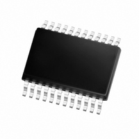
IC POWER METERING-1 PHASE 24SSOP
Manufacturer
Microchip Technology
Datasheets
1.MCP3909T-ISS.pdf
(44 pages)
2.MCP3909T-ISS.pdf
(104 pages)
3.MCP3909-ISS.pdf
(40 pages)
Specifications of MCP3909-I/SS
Package / Case
24-SSOP (0.200", 5.30mm Width)
Input Impedance
390 KOhm
Measurement Error
0.1%
Voltage - I/o High
2.4V
Voltage - I/o Low
0.85V
Current - Supply
2.3mA
Voltage - Supply
4.5 V ~ 5.5 V
Operating Temperature
-40°C ~ 85°C
Mounting Type
Surface Mount
Meter Type
Single Phase
Operating Temperature Range
- 40 C to + 85 C
Mounting Style
SMD/SMT
Supply Voltage Range
4.5V To 5.5V
Digital Ic Case Style
SSOP
No. Of Pins
24
Interface Type
Serial, SPI
Supply Voltage Max
5.5V
Rohs Compliant
Yes
Lead Free Status / RoHS Status
Lead free / RoHS Compliant
For Use With
MCP3909EV-MCU16 - EVALUATION BOARD FOR MCP3909MCP3909RD-3PH1 - REF DESIGN MCP3909 3PH ENGY MTR
Lead Free Status / Rohs Status
Lead free / RoHS Compliant
Available stocks
Company
Part Number
Manufacturer
Quantity
Price

Part Number:
MCP3909-I/SS
Manufacturer:
MICROCHIP/微芯
Quantity:
20 000


MCP3909
The
integration times and, thus, higher frequencies. The
output frequency value can be calculated with the
following equation:
EQUATION 4-2:
The constant HF
digital settings with the
The detailed timings of the output pulses are described
in the Timing Characteristics table (see Section 1.0
“Electrical Characteristics” and
TABLE 4-3:
DS22025A-page 20
Where:
F2
0
0
0
0
1
1
1
1
V
HF
REF
high-frequency
V
V
HF
G
C
0
1
OUT
=
=
=
=
=
F1
0
0
1
1
0
0
1
1
(
Hz
the RMS differential voltage on Channel 0
the RMS differential voltage on Channel 1
the PGA gain on Channel 0 (current
channel)
the frequency constant selected
the voltage reference
C
)
F0
OUTPUT FREQUENCY CONSTANT HF
0
1
0
1
0
1
0
1
depends on the F
=
8.06 V
--------------------------------------------------------------- -
ACTIVE POWER HF
FREQUENCY OUTPUT
EQUATION
Table
output
2048 x F
×
128 x F
64 x F
32 x F
16 x F
64 x F
32 x F
16 x F
4-3.
HF
0
(
V
×
C
HF
REF
V
Figure
C
C
C
C
C
C
1
C
C
OUT
×
)
2
OUT0
G
×
1-1).
HF
has
and F
C
OUT
MCLK/2
MCLK/2
MCLK/2
MCLK/2
MCLK/2
MCLK/2
MCLK/2
MCLK/2
HF
lower
OUT1
C
(Hz)
15
15
15
16
16
16
16
7
4.8.1
The MCP3909 also includes, on each output
frequency, a no-load threshold circuit that will eliminate
any creep effects in the meter. The outputs will not
show any pulse if the output frequency falls below the
no-load threshold. This threshold only applies to the
pulse outputs and does not gate any serial data coming
from either the A/D output or the multiplier output. The
minimum output frequency on F
equal to 0.0015% of the maximum output frequency
(respectively F
selections (see
F2, F1, F0 = 011. In this last configuration, the no-load
threshold feature is disabled. The selection of F
determine the start-up current load. In order to respect
the IEC standards requirements, the meter will have to
be designed to allow start-up currents compatible with
the standards by choosing the FC value matching
these
information on no-load threshold, startup current and
other meter design points, refer to AN994, "IEC Com-
pliant Active Energy Meter Design Using The
MCP3905/6”, (DS00994).
C
(MCLK = 3.58 MHz)
FOR HF
27968.75
HF
109.25
109.25
109.25
219.51
219.51
219.51
219.51
requirements.
C
(Hz)
MINIMAL OUTPUT FREQUENCY
FOR NO-LOAD THRESHOLD
OUT
C
Table 4-2
and HF
(V
REF
C
© 2006 Microchip Technology Inc.
For
HF
= 2.4V)
) for each of the F2, F1 and F0
and
OUT
full-scale AC Inputs
Table
additional
Frequency (Hz) with
OUT0/1
6070.12
27.21
27.21
27.21
47.42
47.42
47.42
47.42
4-3); except when
and HF
applications
OUT
C
will
is
Related parts for MCP3909-I/SS
Image
Part Number
Description
Manufacturer
Datasheet
Request
R

Part Number:
Description:
Energy Metering IC with SPI Interface and Active Power Pulse Output
Manufacturer:
Microchip Technology
Datasheet:
Part Number:
Description:
Power Meter with SPI and Active Power Pulse Output & Internal Oscillator., -40C to +85C, 28-SPDIP, TUBE
Manufacturer:
Microchip Technology
Datasheet:
Part Number:
Description:
Analog to Digital Converters - ADC Energy Meter IC Gain Dynamic Range
Manufacturer:
Microchip Technology

Part Number:
Description:
Manufacturer:
Microchip Technology Inc.
Datasheet:
Part Number:
Description:
Manufacturer:
Microchip Technology Inc.
Datasheet:
Part Number:
Description:
Manufacturer:
Microchip Technology Inc.
Datasheet:
Part Number:
Description:
Manufacturer:
Microchip Technology Inc.
Datasheet:
Part Number:
Description:
Manufacturer:
Microchip Technology Inc.
Datasheet:
Part Number:
Description:
Manufacturer:
Microchip Technology Inc.
Datasheet:
Part Number:
Description:
Manufacturer:
Microchip Technology Inc.
Datasheet: