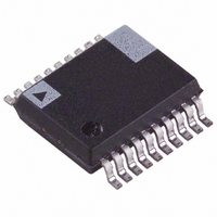
ADE7760ARSRL Analog Devices Inc, ADE7760ARSRL Datasheet - Page 14

ADE7760ARSRL
Manufacturer Part Number
ADE7760ARSRL
Description
IC ENERGY METER W/OCFD 20SSOP TR
Manufacturer
Analog Devices Inc
Datasheet
1.ADE7760ARS.pdf
(24 pages)
Specifications of ADE7760ARSRL
Rohs Status
RoHS non-compliant
Input Impedance
400 KOhm
Measurement Error
0.1%
Voltage - I/o High
2.4V
Voltage - I/o Low
0.8V
Current - Supply
4mA
Voltage - Supply
4.75 V ~ 5.25 V
Operating Temperature
-40°C ~ 85°C
Mounting Type
Surface Mount
Package / Case
20-SSOP (0.200", 5.30mm Width)
Meter Type
Single Phase
Lead Free Status / Rohs Status
Not Compliant
ADE7760
Power Factor Considerations
The method used to extract the active power information from
the instantaneous power signal (by low-pass filtering) is still
valid even when the voltage and current signals are not in
phase. Figure 18 displays the unity power factor condition and
a displacement power factor (DPF = 0.5), that is, current signal
lagging the voltage by 60°. If one assumes the voltage and
current waveforms are sinusoidal, the active power component
of the instantaneous power signal (dc term) is given by
(V × I/2) × cos(60°). This is the correct active power calculation.
Nonsinusoidal Voltage and Current
The active power calculation method also holds true for
nonsinusoidal current and voltage waveforms. All voltage and
current waveforms in practical applications have some har-
monic content. Using the Fourier transform, instantaneous
voltage and current waveforms can be expressed in terms of
their harmonic content:
where:
v(t) is the instantaneous voltage.
V
α
V × I
h
h
2
is the phase angle of the voltage harmonic.
is the rms value of voltage harmonic h.
× cos(60°)
V
t i
) (
) (
t
V × I
=
2
0V
0V
=
I
V
o
CURRENT
VOLTAGE
o
+
Figure 18. Active Power Calculation over PF
VOLTAGE
+
2
2
INSTANTANEOUS
POWER SIGNAL
×
×
h
INSTANTANEOUS
POWER SIGNAL
∑
∞
≠
h
∑
0
∞
≠
I
0
h
V
×
h
×
sin(
sin(
60°
h
ω
h
t
ω
+
INSTANTANEOUS
ACTIVE POWER SIGNAL
t
β
+
h
α
CURRENT
)
INSTANTANEOUS
ACTIVE POWER SIGNAL
h
)
(2)
(1)
Rev. 0 | Page 14 of 24
where:
i(t) is the instantaneous current.
I
I
β
Using Equations 1 and 2, the active power P can be expressed in
terms of its fundamental active power ( P
power ( P
where:
and
As can be seen from Equation 4, a harmonic active power
component is generated for every harmonic, provided that
harmonic is present in both the voltage and current waveforms.
The power factor calculation has previously been shown to be
accurate in the case of a pure sinusoid; therefore, the harmonic
active power must also correctly account for power factor,
because it is made up of a series of pure sinusoids.
Note that the input bandwidth of the analog inputs is 7 kHz
with the internal oscillator frequency of 450 kHz.
HPF and Offset Effects
Equation 5 shows the effect of offset on the active power
calculation. Figure 19 shows the effect of offsets on the active
power calculation in the frequency domain.
As can be seen from Equation 5 and Figure 19, an offset on
Channel 1 and Channel 2 contributes a dc component after
multiplication. Because this dc component is extracted by the
LPF and used to generate the active power information, the
offsets contribute a constant error to the active power calcula-
tion. This problem is easily avoided in the ADE7760 with the
HPF in Channel 1. By removing the offset from at least one
channel, no error component can be generated at dc by the
multiplication. Error terms at cos(ωt) are removed by the LPF
and the digital-to-frequency conversion (see the Digital-to-
Frequency Conversion section).
O
h
h
is the rms value of current harmonic h.
is the dc component.
is the phase angle of the current harmonic.
V
V
(
V
0
) (
P
P
Φ
P
Φ
0
t
×
1
H
+
=
1
h
×
=
I
V
=
=
H
t I
=
1
P
V
):
) (
1
1
α
h
+
1
∑
α
×
∞
=
+
1
V
×
2
h
=
V
cos(
P
−
1
I
−
H
h
×
1
2
β
×
β
cos(
1
ω
I
I
h
1
t
h
))
+
×
Φ
×
V
cos(
1
(
0
)
I
×
0
Φ
+
I
1
h
I
×
)
1
×
cos(
cos(
ω
ω
t
)
t
+
1
))
) and harmonic active
V
=
1
×
I
0
×
cos(
ω
t
)
(4)
(3)
(5)


