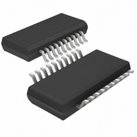
LTC4244CGN-1#TR Linear Technology, LTC4244CGN-1#TR Datasheet - Page 17

LTC4244CGN-1#TR
Manufacturer Part Number
LTC4244CGN-1#TR
Description
IC CTRLR HOT SWAP CPCI 20-SSOP
Manufacturer
Linear Technology
Type
Hot-Swap Controllerr
Datasheet
1.LTC4244IGN-1PBF.pdf
(28 pages)
Specifications of LTC4244CGN-1#TR
Applications
CompactPCI™
Internal Switch(s)
No
Voltage - Supply
3.3V, 5V, ±12V
Operating Temperature
0°C ~ 70°C
Mounting Type
Surface Mount
Package / Case
20-SSOP (0.154", 3.91mm Width)
Lead Free Status / RoHS Status
Contains lead / RoHS non-compliant
APPLICATIO S I FOR ATIO
Calculating R
Determining the most appropriate value for the sense
resistor first requires knowing the maximum current needed
by the load under worst-case conditions. Two other pa-
rameters affect the value of the sense resistor. First is the
tolerance of the LTC4244’s circuit breaker threshold volt-
age. The LTC4244’s nominal circuit breaker threshold
voltage is V
tolerance over process and temperature. Second is the
tolerance (RTOL) of the sense resistor. Sense resistors are
available in RTOL’s of 1%, 2% and 5% and exhibit
temperature coefficients of resistance (TCR’s) between
changes as a function of temperature depends on the
I
sense resistor should accommodate steady-state fault
current levels so that the component is not damaged
before the circuit breaker trips.
Table 2 lists I
gested values of R
part numbers for these resistor values.
Table 2. I
Output Voltage Monitor
The status of all four output voltages is monitored by the
power good function. In addition, the PCI_RST# signal is
logically combined on-chip with the HEALTHY# signal to
create LOCAL_PCI_RST# (see Table 3). As a result,
LOCAL_PCI_RST# will be pulled low whenever HEALTHY#
is pulled high independent of the state of the PCI_RST#
signal.
If any of the output voltages drop below the power good
threshold for more than 14 s, the PWRGD pin will be
2
75ppm/ C and 100ppm/ C. How the sense resistor
• R power being dissipated by it. The power rating of the
R
SENSE
0.005
0.007
0.011
TRIP
(1% RTOL)
CB(NOM)
vs R
TRIP(MIN)
SENSE
SENSE
SENSE
U
= 52mV; however it exhibits 5mV
and I
. Table 7 lists manufacturers and
U
I
TRIP(MIN)
9.31A
TRIP(MAX)
6.6A
4.2A
W
versus some sug-
I
TRIP(MAX)
11.5A
U
8.2A
5.2A
pulled high and the LOCAL_PCI_RST# signal will be
asserted low.
Table 3. LOCAL_PCI_RST# Truth Table
Precharge
The PRECHARGE input and DRIVE output pins are in-
tended for use in generating the 1V precharge voltage that
is used to bias the bus I/O connector pins during board
insertion and extraction. The LTC4244 is also capable of
generating precharge voltages other than 1V. Figure 7
shows a circuit that can be used in applications requiring
a precharge voltage of less than 1V. The circuit in Figure 8
can be used for applications that need precharge voltages
greater than 1V.
Precharge resistors are used to connect the 1V bias volt-
age to the I/O lines with minimal disturbance. Figure 1
shows the precharge application circuit for 5V signaling.
The precharge resistor requirements are more stringent
for 3.3V and Universal Hot Swap boards. If the total leak-
age current on the I/O line is less 2 A, then a 50k resistor
can be connected directly from the 1V bias voltage to the
I/O line. However, many ICs connected to the I/O lines can
have leakage currents up to 10 A. For these applications,
a 10k resistor is used but must be disconnected when the
board is seated as determined by the state of the BD_SEL#
signal. Figure 9 shows a precharge circuit that uses a bus
switch to connect the individual 10k precharge resistors to
the LTC4244’s 1V PRECHARGE pin. The electrical connec-
tion is made (bus switches closed) when the voltage on the
BD_SEL# pin of the plug-in card is pulled-up to 5V
which occurs just after the long pins have made contact.
The bus switches are electrically disconnected when the
short, BD_SEL# connector pin makes contact and the
PCI_RST#
LO
LO
HI
HI
LTC4244/LTC4244-1
HEALTHY#
LO
LO
HI
HI
LOCAL_PCI_RST#
LO
LO
LO
HI
17
42441f
IN
,


