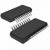
LTC4244IGN-1 Linear Technology, LTC4244IGN-1 Datasheet - Page 23

LTC4244IGN-1
Manufacturer Part Number
LTC4244IGN-1
Description
IC CTRLR HOT SWAP CPCI 20-SSOP
Manufacturer
Linear Technology
Type
Hot-Swap Controllerr
Datasheet
1.LTC4244IGN-1PBF.pdf
(28 pages)
Specifications of LTC4244IGN-1
Applications
CompactPCI™
Internal Switch(s)
No
Voltage - Supply
3.3V, 5V, ±12V
Operating Temperature
-40°C ~ 85°C
Mounting Type
Surface Mount
Package / Case
20-SSOP (0.154", 3.91mm Width)
Family Name
LTC4244-1
Package Type
SSOP N
Operating Supply Voltage (min)
2.25/4.25/10/-10.25V
Operating Supply Voltage (max)
13.5/14.4/-14.4V
Operating Temperature (min)
-40C
Operating Temperature (max)
85C
Operating Temperature Classification
Industrial
Product Depth (mm)
3.99mm
Product Height (mm)
1.5mm
Mounting
Surface Mount
Pin Count
20
Lead Free Status / RoHS Status
Contains lead / RoHS non-compliant
Lead Free Status / RoHS Status
Contains lead / RoHS non-compliant
APPLICATIO S I FOR ATIO
the PC board. For 1 ounce copper foil plating, a general rule
is 1 ampere of DC current per via making sure the via is
properly dimensioned so that solder completely fills the
void. For other plating thicknesses, check with your PCB
fabrication facility.
Design Example
As a design example, consider a CPCI Hot Swap applica-
tion with the following power supply requirements:
Table 4. Design Example Power Supply Requirements
The first step is to select the appropriate values of R
for the 5V and 3.3V supplies. Calculating the value of
R
circuit breaker threshold voltage (47mV for both the 5V
and 3.3V circuit breakers). If a 1% tolerance is assumed
for the sense resistors, then 5m
values yield the following minimum and maximum I
values:
Table 5. I
So sense resistor values of 7m and 5m should suffice
for the 5V and 3.3V supplies, respectively.
The second step is to select MOSFETs for the 5V and 3.3V
supplies. The IRF7457’s on resistance is less than 10.5m
for V
the maximum load current requirement for the 3.3V sup-
ply is 7A, the steady-state power the device may be
required to dissipate is 514mW. The IRF7457 has a
junction-to-ambient thermal resistance of 50 C/Watt. If a
maximum ambient temperature of 50 C is assumed, this
yields a junction temperature of 75.7 C. According to the
IRF7457’s Normalized On-Resistance vs Junction Tem-
SENSE
R
SENSE
GS
VOLTAGE
SUPPLY
–12V
3.3V
12V
is based on I
5m
7m
> 4.5V and a junction temperature of 25 C. Since
5V
TRIP
(1% RTOL)
vs R
SENSE
U
LOAD(MAX)
SUPPLY CURRENT
MAXIMUM DC
U
450mA
100mA
I
TRIP(MIN)
5A
7A
9.3A
6.6A
and the lower limit for the
W
and 7m
CAPACITANCE
I
TRIP(MAX)
2200 F
2200 F
100 F
100 F
LOAD
11.5A
8.2A
U
resistor
SENSE
TRIP
perature curve, the device’s on-resistance can be expected
to increase by about 20% over its room temperature value.
Recalculation of the steady-state values of R
tion temperature yields approximately 12.6m and 81 C,
respectively. The I • R drop across the 3.3V sense resistor
and series MOSFET at maximum load current under these
conditions will be less than 124mV.
The next step is to select appropriate values for C1 and
C
is constrained to less than 6A during power-up (6
medium length connector pins at 1A per pin), then the
inrush current shouldn’t exceed:
This yields:
Hence a C1 value of 330nF 10% should suffice. The value
of C
the duration of the 12V supply inrush current, which
according to Equation 2 is:
In order to guarantee that the LTC4244’s TIMER fault
inhibit period is greater than 24ms, the value of C
should be:
So a value of 82nF ( 10%) should suffice.
TIMER
I
INRUSH
TIMER
C
C
C
t
C
t
. Assuming that the total current for the 5V supply
ON
1
ON
1
TIMER
TIMER
(
(
for this design example will be constrained by
12
12
< 6A – I
I
100
GATE MAX
VOUT
VOUT
I
INRUSH MAX
(
24
24
12
A
)
12
)
LOAD(5VOUT)
1
•
ms
ms I
V V
A
V
LTC4244/LTC4244-1
2200
)
I
550
–
LIMIT MIN
2 100
– .
•
(
•
•
2200
•
1 9
26
TIMER MAX
TIMER MAX
mA
2
(
•
)
F
V
C
A
–
LOAD
(
(
F
F
)
= 6A – 5A = 1A
450
220
–
•
61 8
12
I
LOAD MAX
mA
)
)
•
nF
.
V
12
nF
(
V
24
)
ms
ON
and junc-
23
TIMER
(12)
(13)
(14)
(15)
42441f
5V


