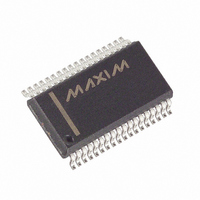
MAX5965BUAX+ Maxim Integrated Products, MAX5965BUAX+ Datasheet - Page 20

MAX5965BUAX+
Manufacturer Part Number
MAX5965BUAX+
Description
IC PSE CTRLR FOR POE 36SSOP
Manufacturer
Maxim Integrated Products
Type
Power Over Ethernet Controller (PoE)r
Datasheet
1.MAX5965AUAXT.pdf
(53 pages)
Specifications of MAX5965BUAX+
Applications
IP Phones, Power over LAN, Network Routers and Switches
Internal Switch(s)
No
Voltage - Supply
2.4 V ~ 3.6 V
Operating Temperature
0°C ~ 85°C
Mounting Type
Surface Mount
Package / Case
36-BSOP (0.300", 7.5mm Width)
Supply Voltage (max)
60 V
Supply Voltage (min)
32 V
Power Dissipation
1388.9 mW
Operating Temperature Range
0 C to + 85 C
Mounting Style
SMD/SMT
Lead Free Status / RoHS Status
Lead free / RoHS Compliant
High-Power, Quad, Monolithic, PSE Controllers
for Power over Ethernet
A sense resistor R
V
conditions, the voltage across R
the threshold V
internal current-limiting circuit regulates the GATE_ volt-
age, limiting the current to I
transient conditions, if V
than 1V, a fast pulldown circuit activates to quickly
recover from the current overshoot. During startup, if
the current-limit condition persists, when the startup
timer, t
STRT_FLT_ bit is set. In the normal powered state, the
MAX5965A/MAX5965B check for overcurrent condi-
tions as determined by V
The t
ous overcurrent period. The t
when V
pace when V
ment for the t
ed short-duration overcurrents. When the counter
reaches the t
power off the port and assert the IMAX_FLT_ bit. For a
continuous overstress, a fault latches exactly after a
period of t
ICUT registers R2Ah[6:4], R2Ah[2:0], R2Bh[6:4],
R2Bh[2:0], and the IVEE bits in register R29h[1:0]. See
the High-Power Mode section for more information on
the ICUT register.
Figure 2. PGOOD_ Timing
20
EE
PGOOD_
monitors the load current. Under normal operating
______________________________________________________________________________________
POK_
FAULT
RS
START
FAULT
exceeds V
counter sets the maximum allowed continu-
RS
FAULT
, times out, the port shuts off, and the
FAULT
. V
drops below V
SU_LIM
SU_LIM
S
t
counter allows for detecting repeat-
PGOOD
FLT_LIM
connected between SENSE_ and
limit, the MAX5965A/MAX5965B
. If V
RS
Overcurrent Protection
FLT_LIM
is programmable through the
exceeds V
LIM
and decreases at a slower
RS
FAULT
FLT_LIM
S
exceeds V
= V
(V
= ~88% of V
RS
SU_LIM
counter increases
. A slower decre-
) never exceeds
SU_LIM
/R
SU_LIM
S
by more
. During
SU_LIM
, an
.
After power-off due to an overcurrent fault, and if the
RSTR_EN bit is set, the t
reset but starts decrementing at the same slower pace.
The MAX5965A/MAX5965B allow the port to be pow-
ered on only when the t
feature sets an automatic duty-cycle protection to the
external MOSFET avoiding overheating.
The MAX5965A/MAX5965B continuously flag when the
current exceeds the maximum current allowed for the
class as indicated in the CLASS status register. When
class overcurrent occurs, the MAX5965A/MAX5965B
set the IVC_ bit in register R09h.
The ICUT register determines the maximum current lim-
its allowed for each port of the MAX5965A/MAX5965B.
The 3 ICUT bits (R2Ah[6:4], R2Ah[2:0], R2Bh[6:4], and
R2Bh[2:0]) allow programming of the current-limit and
overcurrent thresholds in excess of the IEEE standard
limit (see Tables 34a, 34b, and 34c). The ICUT regis-
ters can be written to directly through the I
when CL_DISC (R17h[2]) is set to 0 (see Table 3). In
this case, the current limit of the port is configured
regardless of the status of the classification.
By setting the CL_DISC bit to 1, the MAX5965A/
MAX5965B automatically set the ICUT register based
upon the classification result of the port. See Table 3
and the Register Map and Description section.
When CL_DISC (R17h[2]) is set to 0, high-power mode
is configured by setting the ICUT bits to any combina-
tion other than 000, 110, or 111 (note that 000 is the
default value for the IEEE standard limit). See Table 3
and the Register Map and Description section.
During startup and normal operation, an internal circuit
senses the voltage at OUT_ and reduces the current-
limit value when (V
function helps to reduce the power dissipation on the
FET. The current limit eventually reduces down to 1/3 of
I
high-power mode, the foldback starts when (V
V
current limit (I
back current (V
LIM
EE
) > 10V (see Figure 3b). In high-power mode, the
when (V
ICUT Register and High-Power Mode
OUT
LIM
TH_FB
_ - V
) is reduced down to minimum fold-
OUT
/R
EE
S
_ - V
) when (V
FAULT
FAULT
) > 48V (see Figure 3a). For
EE
timer is not immediately
counter is at zero. This
) > 28V. The foldback
Foldback Current
OUT
High-Power Mode
_ - V
ICUT Register
EE
2
C interface
) > 48V.
OUT
_ -


