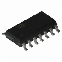
MIC2586R-2BM Micrel Inc, MIC2586R-2BM Datasheet - Page 13

MIC2586R-2BM
Manufacturer Part Number
MIC2586R-2BM
Description
IC CTRLR/SEQ HOT SWAP 14-SOIC
Manufacturer
Micrel Inc
Type
Hot-Swap Controllerr
Datasheet
1.MIC2586R-1YM.pdf
(17 pages)
Specifications of MIC2586R-2BM
Applications
General Purpose
Internal Switch(s)
No
Voltage - Supply
10 V ~ 80 V
Operating Temperature
-40°C ~ 85°C
Mounting Type
Surface Mount
Package / Case
14-SOIC (0.154", 3.90mm Width)
Family Name
MIC2586
Package Type
SOIC
Operating Supply Voltage (min)
10V
Operating Supply Voltage (max)
80V
Operating Temperature (min)
-40C
Operating Temperature (max)
85C
Operating Temperature Classification
Industrial
Product Depth (mm)
3.9mm
Product Height (mm)
1.45mm
Mounting
Surface Mount
Pin Count
14
Lead Free Status / RoHS Status
Contains lead / RoHS non-compliant
Applications Information
External ON/OFF Control
The MIC2586/MIC2586R have an ON pin input that is used
to enable the controller to commence a start-up sequence
upon card insertion or to disable controller operation upon
card removal. In addition, the ON pin can be used to reset
the MIC2586/MIC2586R’s internal electronic circuit breaker
in the event of a load current fault. To reset the electronic
circuit breaker, the ON pin is toggled LOW then HIGH. The
ON pin is internally connected to an analog comparator with
80mV of hysteresis. When the ON pin voltage falls below its
internal V
low. The GATE pin will be held low until the ON pin voltage is
above its internal V
threshold voltage level is programmed using a resistor divider
(R1 & R2) as shown in the "Typical Application” circuit. The
equations to set the trip points are shown below. For the
following example, the external circuit's ON threshold is set
to V
Office power distribution applications.
Given V
suggested value for R2 is that which will provide
approximately 100µA of current through the voltage divider
chain at V
point:
The closest standard 1% value for R2 is 13kΩ. Now, solving
for R1 yields:
The closest standard 1% value for R1 is 357kΩ.
Using standard 1% resistor values, the external circuit's
nominal ON and OFF thresholds are:
In solving for V
Output Voltage Power-is-Good Detection
The MIC2586/86R includes an analog comparator used to
monitor the output voltage of the controller through an
external resistor divider as shown in the "Typical Application"
circuit. The FB input pin is connected to the non-inverting
input and is compared against an internal reference voltage.
The analog comparator exhibits a hysteresis of 80mV.
Micrel
October 2004
V
V
ONH(EX)
R2 =
R1= R2 ×
V
ONH(EX)
ON(EX)
OFF(EX)
ONH
V
ONL
100
CC
ONH(TYP)
= +37V, a value commonly used in +48V Central
= +36V
= V
= +34V
and R2, a value for R1 can be determined. A
= V
⎡
⎢
⎢
⎣
threshold, the GATE pin is immediately pulled
µ
⎛
⎜ ⎜
⎝
ONH
OFF(EX)
A
V
V
ONH(TYP)
ONH(EX)
ONH
=
×
⎛
⎜
⎝
1.313V
100
ONH
. This yields the following as a starting
, replace V
R1+ R2
R2
⎞
⎟ ⎟ −1
⎠
µ
threshold. The external circuit's ON
A
⎤
⎥
⎥
⎦
= 13.13kΩ
= 13kΩ ×
⎞
⎟
⎠
ONH
with V
⎡
⎢
⎣
⎛
⎜
⎝
1.313V
37V
ONL
in Equation 10.
⎞
⎟ −1
⎠
⎤
⎥ = 353.3kΩ
⎦
(10)
13
Setting the "Power-is-Good" threshold for the circuit follows a
similar approach as setting the circuit's ON/OFF input
voltage. The equations to set the trip points are shown
below. For the following +48V telecom application, power-is-
good output signal PWRGD1 (or /PWRGD1) is to be de-
asserted when the output supply voltage is lower than +48V-
10% (+43.2V).
Given V
suggested value for R6 is that which will provide
approximately 100µA of current through the voltage divider
chain at V
equation as a starting point:
The closest standard 1% value for R6 is 12.4kΩ. Now,
solving for R5 yields:
The closest standard 1% value for R5 is 422kΩ.
Using standard 1% resistor values, the external circuit's
nominal "power-is-good" and "power-is-not-good" output
voltages are:
In solving for V
11.
Sense Resistor Selection
The sense resistor is nominally valued at:
where V
voltage (47mV) and I
current level to trip the internal circuit breaker.
To accommodate worse-case tolerances in the sense
resistor (for a ±1% initial tolerance, allow ±3% tolerance for
variations over time and temperature) and circuit breaker
threshold voltages, a slightly more detailed calculation must
be used to determine the minimum and maximum hot swap
load currents.
The MIC2586/MIC2586R has a minimum current limit
threshold voltage of 39mV, thus the minimum hot swap load
current is determined where the sense resistor is 3% high:
R5 = R6 ×
V
V
R6 =
I
V
R
HOT_SWAP(MIN)
OUT(NOT GOOD)
OUT(GOOD)
OUT(NOT GOOD)
SENSE
FBL
TRIP(TYP)
⎡
⎢
⎢
⎣
V
100
⎛
⎜ ⎜
⎝
FBL(TYP)
V
=
OUT(NOT GOOD)
and R6, a value for R5 can be determined. A
OUT(NOT GOOD)
I
HOT_SWAP(N
V
µ
FBL(TYP)
= +46V
A
V
OUT(GOOD)
TRIP(TYP)
=
= V
=
is the nominal circuit breaker threshold
= +43.2V
(
1.03 ×R
1.233V
100
FBL
HOT_SWAP(NOM)
OM)
⎞
⎟ ⎟ − 1
⎠
×
µ
, substitute V
39mV
A
⎛
⎜
⎝
= V
R5 + R6
⎤
⎥
⎥
⎦
SENSE(NOM)
= 12.33kΩ
= 12.4kΩ ×
R6
FBL
. This yields the following
⎞
⎟
⎠
is the nominal inrush load
)
=
FBH
⎡
⎢
⎣
⎛
⎜
⎝
R
1.233V
MIC2586/MIC2586R
43.2V
37.9mV
SENSE(NOM)
for V
FBL
(408) 955-1690
⎞
⎟ − 1
⎠
M9999-102204
⎤
⎥ = 422kΩ
⎦
in Equation
(11)
(12)


