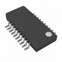
MAX3766EEP Maxim Integrated Products, MAX3766EEP Datasheet - Page 9

MAX3766EEP
Manufacturer Part Number
MAX3766EEP
Description
IC LASR DRVR 622MBPS 5.5V 20QSOP
Manufacturer
Maxim Integrated Products
Type
Laser Diode Driver (Fiber Optic)r
Datasheet
1.MAX3766EEP.pdf
(20 pages)
Specifications of MAX3766EEP
Data Rate
622Mbps
Number Of Channels
1
Voltage - Supply
4.5 V ~ 5.5 V
Current - Supply
25mA
Current - Modulation
60mA
Current - Bias
80mA
Operating Temperature
-40°C ~ 85°C
Package / Case
20-QSOP
Mounting Type
Surface Mount
Operating Supply Voltage
5 V
Supply Current
25 mA
Maximum Operating Temperature
+ 85 C
Maximum Power Dissipation
590 mW
Minimum Operating Temperature
- 40 C
Mounting Style
SMD/SMT
Lead Free Status / RoHS Status
Contains lead / RoHS non-compliant
Available stocks
Company
Part Number
Manufacturer
Quantity
Price
Company:
Part Number:
MAX3766EEP
Manufacturer:
MAXIM
Quantity:
20
Part Number:
MAX3766EEP
Manufacturer:
MAXIM/美信
Quantity:
20 000
Company:
Part Number:
MAX3766EEP+
Manufacturer:
Maxim
Quantity:
670
Company:
Part Number:
MAX3766EEP+
Manufacturer:
HITTITE
Quantity:
5 000
Part Number:
MAX3766EEP+
Manufacturer:
MAXIM/美信
Quantity:
20 000
Company:
Part Number:
MAX3766EEP+T
Manufacturer:
3M
Quantity:
230
Transmitters employing a laser with monitor photodiode
can use the APC circuit to maintain constant power,
regardless of laser threshold changes due to temperature
and aging. The APC circuit consists of the POWERSET
current mirror and the monitor diode amplifier.
The POWERSET current mirror provides an accurate
method of programming the back facet monitor photo-
diode current, which is assumed to be proportional to
laser output power. An external resistor from REF1 to
POWERSET programs the current in the unity-gain cur-
rent mirror. R
The monitor-diode amplifier senses the current from the
monitor photodiode at MD, provides gain, and adjusts
the laser bias programming current (I
diode amplifier forces the monitor-diode current to
equal the current programmed at POWERSET. The
monitor-diode amplifier can reduce the laser bias pro-
gramming current, but cannot increase it. Therefore,
the APC circuit can adjust laser bias current between 0
and the setting determined by R
When the APC feedback loop is closed, the voltage at
MD is approximately 2V below V
close due to excess or insufficient photocurrent, a fail-
ure is detected by the failure-detection circuit. Internal
circuitry prevents the voltage at MD from dropping
below V
The stability and time constant of the APC feedback
loop is determined by an external compensation
capacitor (C
pensation capacitor from V
Typical Application Circuits, to ensure a smooth start-
up at power-on or transmitter enable.
If a monitor diode is not available, the APC feature can
be disabled by connecting R
leaving MD unconnected.
Figure 3 shows a simplified schematic of the failure-
detection circuit. The failure-detection circuit senses
two conditions. First, if the APC control loop cannot
control the monitor current due to laser undercurrent,
overcurrent, or a fault condition, a window comparator
detects that V
asserts the failure signal. Second, if REF1 is shorted to
the positive supply (or any another voltage above the
normal operating level), a comparator detects this con-
dition and asserts the failure signal. If left undetected,
Automatic Power Control and Safety Shutdown
CC
R
- 3.2V.
POWERSET
POWERSET
MD
MD
) of at least 0.1µF. Connect the com-
_______________________________________________________________________________________
is above or below V
Automatic Power Control
can be estimated as follows:
=
622Mbps LAN/WAN Laser Driver with
1.55V
I
MOD
CC
POWERSET
BIASMAX
Failure Detection
CC
to MD, as shown in
− 300Ω
. If the loop cannot
LBP
.
). The monitor-
CC
to GND and
- 2V and
the reference voltage would rise, the current at POWER-
SET would increase, and the APC loop would attempt to
add laser current beyond the intended value.
Either failure condition causes the FAIL output to assert
TTL low. The FAIL output buffer is an open-collector
output and is designed to operate with a 5.1kΩ external
pull-up resistor.
The safety circuit includes the digital logic needed to
provide a latched internal shutdown signal (SHDN) for
disabling the laser if a failure condition exists. The
MAX3766 produces less than 20µA of total laser cur-
rent when disabled by safety features or by the
ENABLE input. Figure 4 is a simplified schematic of the
safety circuit.
If ENABLE is low or open, the laser bias and modula-
tion outputs are disabled by SHDN, regardless of the
state of the safety logic. The TTL-compatible ENABLE
input is internally pulled low with a 100kΩ resistor.
There are two useful safety configurations: failure
indication and latched shutdown.
Select the failure-indication configuration by connecting
SAFETY to ground. In this configuration, a failure condi-
tion is reported at FAIL, but does not cause a latched
shutdown. This configuration requires no additional cir-
cuitry for start-up.
Figure 3. Failure-Detection Circuit (Simplified)
V
BANDGAP
V
V
REF1
MD
V
CC
2V
0.5V
Failure-Indication Configuration
200mV
200mV
Safety/Start-Up Circuit
FAILURE
(INTERNAL)
9


