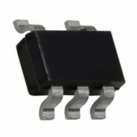
FAN5331SX Fairchild Semiconductor, FAN5331SX Datasheet - Page 7

FAN5331SX
Manufacturer Part Number
FAN5331SX
Description
IC LED DRVR WHITE BCKLGT SOT23-5
Manufacturer
Fairchild Semiconductor
Type
Backlight, White LED (Serial Interface)r
Datasheet
1.FAN5331SX.pdf
(10 pages)
Specifications of FAN5331SX
Topology
PWM, Step-Up (Boost)
Number Of Outputs
1
Internal Driver
Yes
Type - Primary
General Purpose
Frequency
1.15MHz ~ 1.85MHz
Voltage - Supply
2.7 V ~ 5.5 V
Voltage - Output
20V
Mounting Type
Surface Mount
Package / Case
SOT-23-5, SC-74A, SOT-25
Operating Temperature
-40°C ~ 85°C
Current - Output / Channel
50mA
Internal Switch(s)
Yes
Efficiency
88%
Operating Supply Voltage (typ)
3.3/5V
Operating Temperature (min)
-40C
Operating Temperature (max)
85C
Operating Temperature Classification
Industrial
Package Type
SOT-23
Pin Count
5
Mounting
Surface Mount
Operating Supply Voltage (min)
2.7V
Operating Supply Voltage (max)
5.5V
Low Level Output Current
50 mA
Operating Supply Voltage
2.7 V to 5.5 V
Maximum Supply Current
3 mA
Maximum Operating Temperature
+ 85 C
Mounting Style
SMD/SMT
Minimum Operating Temperature
- 40 C
Primary Input Voltage
5.5V
No. Of Outputs
1
Output Voltage
20V
No. Of Pins
5
Operating Temperature Range
-40°C To +85°C
Peak Reflow Compatible (260 C)
Yes
Leaded Process Compatible
Yes
Rohs Compliant
Yes
Dc
N/A
Lead Free Status / RoHS Status
Lead free / RoHS Compliant
Other names
FAN5331SXTR
FAN5331SX_NL
FAN5331SX_NLTR
FAN5331SX_NLTR
FAN5331SX_NL
FAN5331SX_NLTR
FAN5331SX_NLTR
Available stocks
Company
Part Number
Manufacturer
Quantity
Price
Company:
Part Number:
FAN5331SX
Manufacturer:
FSC
Quantity:
3 000
Part Number:
FAN5331SX
Manufacturer:
FAIRCHILD/ن»™ç«¥
Quantity:
20 000
Part Number:
FAN5331SX_NL
Manufacturer:
FAIRCHILD/ن»™ç«¥
Quantity:
20 000
FAN5331 Rev. 1.0.1
The inductor saturation current should be rated around 1A,
which is the threshold of the internal current limit circuit. This
limit is reached only during the start-up and with heavy load
condition; when this event occurs the converter can shift over in
discontinuous conduction mode due to the automatic turn-off of
the switching transistor, resulting in higher ripple and reduced
efficiency.
Some recommended inductors are suggested in the table
below:
Capacitors Selection
For best performance, low ESR input and output capacitors are
required. Ceramic capacitors in the range 4.7µF to 10µF, placed
as close to the IC pins, are recommended for the lower input
and output ripple. The output capacitor voltage rating should be
according to the V
A feed forward capacitor C
mended value (R
suggested in the table below.
Diode Selection
The external diode used for rectification is usually a Schottky
diode. Its average forward current and reverse voltage maxi-
mum ratings should exceed the load current and the voltage at
the output of the converter respectively. A barrier Schottky diode
such as BAT54 is preferred, due to its lower reverse current over
the temperature range.
Care should be taken to avoid any short circuit of V
even with the IC disabled, since the diode can be instantly dam-
aged by the excessive current.
Thermal Shutdown
When the die temperature exceeds 150°C, a reset occurs and
will remain in effect until the die cools to 130°C, at that time the
circuit will be allowed to restart.
Inductor
Capacitor
Value
Value
10µH
10µH
10µH
4.7µF
4.7µF
Table 2: Recommended Capacitors
Table 1: Recommended Inductors
Panasonic
Vendor
Coilcraft
Murata
1
OUT
Panasonic
x C
Vendor
Murata
setting.
F
) is around 18µS. Some capacitors are
F
LQS66SN100M03L
, is required for stability. The recom-
DO1605T-103Mx
Part Number
ELL6GM100M
GRM31CR61C475
Part Number
ECJ3YB1C475K
Lower Profile
Comment
Small Size
Efficiency
OUT
(1.6mm)
Highest
to GND,
7
PCB Layout Recommendations
The inherently high peak currents and switching frequency of
power supplies require careful PCB layout design. Therefore,
use wide traces for high current paths and place the input
capacitor, the inductor, and the output capacitor as close as
possible to the integrated circuit terminals. The resistor divider
that sets the output voltage should be routed away from the
inductor to avoid RF coupling. A four layer PCB with at least one
ground plane connected to the pin 2 of the IC is recommended.
This ground plane acts as an electromagnetic shield to reduce
EMI and parasitic coupling between components.
Application Examples
1. LED Driver
One or more serial LED strings can be driven with a constant
current, set by the series resistor, given by
V
Figure 6. Low Noise Boost LED Driver
IN
ON
C
4.7µF
Figure 5. Recommended Layout
IN
OFF
2.7V to 5.5V
5
4
V
SHDN
IN
I
LED
L
µH
GND
FB
SW
=
1
3
2
1.23V
--------------- -
R1
BAT54
4.7µF
C
OUT
R1
www.fairchildsemi.com
R2
V
OUT


