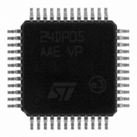
STP24DP05BTR STMicroelectronics, STP24DP05BTR Datasheet - Page 17

STP24DP05BTR
Manufacturer Part Number
STP24DP05BTR
Description
IC LED DRIVER LINEAR 48-TQFP
Manufacturer
STMicroelectronics
Type
Linear (Serial Interface)r
Datasheet
1.STP24DP05BTR.pdf
(26 pages)
Specifications of STP24DP05BTR
Constant Current
Yes
Number Of Outputs
24
Internal Driver
Yes
Type - Primary
General Purpose
Type - Secondary
RGB
Frequency
25MHz
Voltage - Supply
3 V ~ 5.5 V
Voltage - Output
20V
Mounting Type
Surface Mount
Package / Case
48-TQFP Exposed Pad, 48-eTQFP, 48-HTQFP, 48-VQFP
Operating Temperature
-40°C ~ 125°C
Current - Output / Channel
80mA
Internal Switch(s)
Yes
Low Level Output Current
- 10000 uA (Typ)
High Level Output Current
10000 uA (Typ)
Operating Supply Voltage
3.3 V to 5 V
Maximum Supply Current
40 mA
Maximum Operating Temperature
+ 125 C
Mounting Style
SMD/SMT
Minimum Operating Temperature
- 40 C
Led Driver Application
LED Displays
Topology
Constant Current
No. Of Outputs
24
Output Current
80mA
Output Voltage
20V
Input Voltage
3V To 5.5V
Operating Temperature Range
-40°C To +125°C
For Use With
497-8490 - BOARD EVAL STP24DP05/STM32 BASED
Lead Free Status / RoHS Status
Lead free / RoHS Compliant
Efficiency
-
Topology
-
Lead Free Status / Rohs Status
Lead free / RoHS Compliant
Other names
497-8283-2
Available stocks
Company
Part Number
Manufacturer
Quantity
Price
Company:
Part Number:
STP24DP05BTR
Manufacturer:
STMicroelectronics
Quantity:
10 000
STP24DP05
7.4
Figure 14. SPI sequence to enter in detection mode - time diagram
After these five CLK cycles the device goes into the “error detection mode” and at the 6
rise front of CLK the SDI data are ready for the sampling.
Phase two: “error detection”
The eight data bits must be set “1” in order to set ON all the outputs during the detection.
The data are latched by LE\DM and after that the outputs are ready for the detection
process. When the micro controller switches the OE-R\DM to LOW, the device drives the
LEDs in order to analyze if an OPEN or SHORT condition has occurred.
Figure 15. Detection diagram
The LEDs status will be detected at least in 1 microsecond and after this time the
microcontroller sets OE-R\DM in HIGH state and the output data detection result will go to
the microprocessor via SDO.
Detection mode and normal mode use both the same format data. As soon as all the
detection data bits are available on the serial line, the device may go back to normal mode
of operation.
OE-R\DM
LE\DM
Doc ID 14714 Rev 4
Feature description
17/26
th


