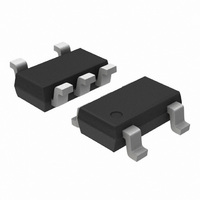
CAT4201TD-GT3 ON Semiconductor, CAT4201TD-GT3 Datasheet - Page 9

CAT4201TD-GT3
Manufacturer Part Number
CAT4201TD-GT3
Description
IC LED DRIVER HIGH BRIGHT TSOT-5
Manufacturer
ON Semiconductor
Type
HBLED Driverr
Specifications of CAT4201TD-GT3
Topology
PWM, Step-Down (Buck)
Number Of Outputs
1
Internal Driver
Yes
Type - Primary
Automotive, Backlight
Type - Secondary
High Brightness LED (HBLED)
Frequency
1MHz
Voltage - Supply
6.5 V ~ 36 V
Voltage - Output
36V
Mounting Type
Surface Mount
Package / Case
TSOT-23-5, TSOT-5, TSOP-5
Operating Temperature
-40°C ~ 125°C
Current - Output / Channel
350mA
Internal Switch(s)
Yes
Efficiency
94%
Number Of Segments
1
Operating Supply Voltage
6.5 V to 28 V
Maximum Supply Current
0.4 mA
Maximum Operating Temperature
+ 125 C
Mounting Style
SMD/SMT
Minimum Operating Temperature
- 40 C
Lead Free Status / RoHS Status
Lead free / RoHS Compliant
Other names
CAT4201TD-GT3TR
Available stocks
Company
Part Number
Manufacturer
Quantity
Price
APPLICATION INFORMATION
Input Voltage Range
adequate regulation is set by the cathode terminal voltage of
the LED string (i.e., the VBAT voltage minus the LED string
voltage). When the LED cathode terminal falls below 3 V,
a loss of regulation occurs.
experience supply “dropout” conditions, it is recommended
that the CTRL input be used to sense the LED cathode
voltage. The CTRL pin can either be tied directly to the
cathode terminal (for Lamp Replacement) or connected via
a pass−transistor for PWM lighting applications.
dropout, when the CTRL pin is configured to sense the LED
cathode voltage.
Inductor Selection
value is recommended to provide suitable switching
frequency across a wide range of input supply values. For
LED current of 150 mA or less, a 33 mH or 47 mH inductor
is more suitable.
equals or exceeds twice the programmed LED current. For
example, when driving LEDs at 350 mA, an inductor with
at least 700 mA current rating must be used. Minor
improvements in efficiency can be achieved by selecting
inductors with lower series resistance.
Table 7. SUMIDA INDUCTORS
CDRH6D26−100
CDRH6D26−220
CDRH6D28−330
CDRH6D28−470
CDRH6D28−560
The minimum supply voltage required to maintain
For applications which may occasionally need to
Figure 23 shows the regulation performance obtained in
For 350 mA LED current drive levels, a 22 mH inductor
The inductor must have a maximum current rating which
400
300
200
100
Part Number
Figure 23. “Dropout” Configured LED Current
0
0
(as shown in Typical Application on page 1)
1
L (mH)
CTRL VOLTAGE [V]
10
22
33
47
56
2
I Rated (A)
3
0.92
0.73
1.5
1.0
0.8
300 mA
150 mA
4
LED Current (A)
0.35
0.35
0.35
0.35
0.35
5
http://onsemi.com
6
9
Capacitor Selection
LED ripple current within ±15% of nominal for most
applications. If needed, a larger capacitor can be used to
further reduce the LED current ripple. Any resistance in
series with the LED (0.5 W or more) contributes to reduce
the ripple current. The capacitor voltage rating should be
equivalent to the maximum expected supply voltage so as to
allow for “Open−LED” fault conditions. The capacitor
value is independent of the switching frequency or the
overall efficiency.
minimize the input current ripple generated on the supply.
Using a larger capacitor value further reduces the ripple
noise appearing on the supply rail.
voltage, X5R or X7R dielectric capacitors are recommended.
Schottky Diode
must be greater than the peak current flowing through the
inductor. Also the continuous current rating of the Schottky
must be greater than the average LED current. The voltage
rating of the diode should be greater than the peak supply
voltage transient preventing any breakdown or leakage.
ON Semiconductor Schottky diode MBR0540 (40 V,
500 mA rated) is recommended. Schottky diodes rated at
400 mA (or higher) continuous current are fine for most
applications.
NOTE:
Dimming Methods
described below. The first method is to PWM on the control
pin, the other method is to turn on and off a second resistor
connected to the RSET pin and connected in parallel with R1.
PWM on CTRL Pin
dimming the LEDs when tied to the CTRL pin. The duty
cycle which is the ratio between the On time and the total
cycle time sets the dimming factor. The recommended PWM
frequency on the CTRL pin is between 100 Hz and 2 kHz.
A 10 mF ceramic capacitor C2 across the LED(s) keeps the
A 4.7 mF ceramic input capacitor C1 is recommended to
If a constant capacitance is needed across temperature and
The peak repetitive current rating of the Schottky diode
Two methods for PWM dimming control on the LEDs are
A PWM signal from a microprocessor can be used for
Schottky diodes with extremely low forward voltages
(V
increase in the LED current.
Figure 24. PWM at 1 kHz on CTRL Pin
F
) are not recommended, as they may cause an


