LP55281TL/NOPB National Semiconductor, LP55281TL/NOPB Datasheet - Page 22
LP55281TL/NOPB
Manufacturer Part Number
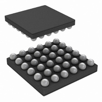
LP55281TL/NOPB
Description
IC LED DRIVER RGB 36-USMD
Manufacturer
National Semiconductor
Series
PowerWise®r
Type
RGB LED Driverr
Datasheet
1.LP55281RLNOPB.pdf
(28 pages)
Specifications of LP55281TL/NOPB
Constant Current
Yes
Topology
PWM, Step-Up (Boost)
Number Of Outputs
12
Internal Driver
Yes
Type - Primary
Light Management Unit (LMU)
Type - Secondary
Color, RGB
Frequency
1MHz ~ 2MHz
Voltage - Supply
3 V ~ 5.5 V
Voltage - Output
4 V ~ 5.3 V
Mounting Type
Surface Mount
Package / Case
36-MicroSMD
Operating Temperature
-30°C ~ 85°C
Current - Output / Channel
300mA
Internal Switch(s)
Yes
Efficiency
88%
For Use With
LP55281RLEV - BOARD EVAL FOR LP5528 RGB DRIVER
Lead Free Status / RoHS Status
Lead free / RoHS Compliant
Other names
LP55281TLTR


www.national.com
"negative acknowledge" still includes the acknowledge clock
pulse (generated by the master), but the SDA line is not pulled
down.
Addressing Transfer Formats
Each device on the bus has a unique slave address. The
LP55281 operates as a slave device with 7-bit address.
LP55281 I
choices. The LP55281 address is 4Ch (SI/A0 = 0) or 4Dh
(SI/A0 = 1) as selected with SI/A0 pin. If eighth bit is used
for programming, the 8
Before any data is transmitted, the master transmits the ad-
dress of the slave being addressed. The slave device should
send an acknowledge signal on the SDA line, once it recog-
nizes its address.
The slave address is the first seven bits after a Start Condi-
tion. The direction of the data transfer (R/W) depends on the
bit sent after the slave address (the eighth bit).
When the slave address is sent, each device in the system
compares this slave address with its own. If there is a match,
the device considers itself addressed and sends an acknowl-
edge signal. Depending upon the state of the R/W bit (1 for
read, 0 for write), the device acts as a transmitter or a receiver.
Control Register Write Cycle
•
•
•
•
•
•
•
•
Master device generates start condition
Master device sends slave address (7 bits) and the data
direction bit (r/w=0).
Slave device sends acknowledge signal if the slave
address is correct.
Master sends control register address (8 bits).
Slave sends acknowledge signal.
Master sends data byte to be written to the addressed
register.
Slave sends acknowledge signal.
If master will send further data bytes, the control register
address will be incremented by one after acknowledge
signal
2
C address is pin selectable from two different
I
2
C Device Address
th
bit is 1 for read and 0 for write.
Register Read Format
20201151
22
•
Control Register Read Cycle
•
•
•
•
•
•
•
•
•
•
•
< > Data from master, [ ] data from slave
Data Read
Data Write
Write cycle ends when the master creates stop condition.
Master device generates a start condition.
Master device sends slave address (7 bits) and the data
direction bit (r/w=0).
Slave device sends acknowledge signal if the slave
address is correct.
Master sends control register address (8 bits).
Slave sends acknowledge signal.
Master device generates repeated start condition.
Master sends the slave address (7 bits) and the data
direction bit (r/w=1).
Slave sends acknowledge signal if the slave address is
correct.
Slave sends data byte from addressed register.
If the master device sends acknowledge signal, the control
register address will be incremented by one. Slave device
sends data byte from addressed register.
Read cycle ends when the master does not generate
acknowledge signal after data byte and generates stop
condition.
Address Mode
<Start Condition>
<Slave Address><r/w = 0>[Ack]
<Register Address>[Ack]
<Repeated Start Condition>
<Slave Address><r/w = 1>[Ack]
[Register Data]<Ack or NAck>
...additional reads from subsequent
register address possible
<Stop Condition>
<Start Condition>
<Slave Address><r/w = 0>[Ack]
<Register Address>[Ack]
<Register Data>[Ack]
...additional writes to subsequent
register address possible
<Stop Condition>
20201194
Related parts for LP55281TL/NOPB
Image
Part Number
Description
Manufacturer
Datasheet
Request
R

Part Number:
Description:
National Semiconductor [8-Bit D/A Converter]
Manufacturer:
National Semiconductor
Datasheet:
Part Number:
Description:
National Semiconductor [Media Coprocessor]
Manufacturer:
National Semiconductor
Datasheet:
Part Number:
Description:
Digitally Controlled Tone and Volume Circuit with Stereo Audio Power Amplifier, Microphone Preamp Stage and National 3D Sound
Manufacturer:
National Semiconductor
Datasheet:
Part Number:
Description:
Digitally Controlled Tone and Volume Circuit with Stereo Audio Power Amplifier, Microphone Preamp Stage and National 3D Sound
Manufacturer:
National Semiconductor
Datasheet:
Part Number:
Description:
AC97 Rev 2 Codec with Sample Rate Conversion and National 3D Sound
Manufacturer:
National Semiconductor
Part Number:
Description:
Manufacturer:
National Semiconductor
Datasheet:
Part Number:
Description:
Manufacturer:
National Semiconductor
Datasheet:
Part Number:
Description:
General Purpose, Low Voltage, Low Power, Rail-to-Rail Output Operational Amplifiers
Manufacturer:
National Semiconductor
Datasheet:
Part Number:
Description:
8-bit 20 MSPS flash A/D converter.
Manufacturer:
National Semiconductor
Datasheet:
Part Number:
Description:
Low Noise Quad Operational Amplifier
Manufacturer:
National Semiconductor
Datasheet:
Part Number:
Description:
Quad Differential Line Receivers
Manufacturer:
National Semiconductor
Datasheet:
Part Number:
Description:
Quad High Speed Trapezoidal? Bus Transceiver
Manufacturer:
National Semiconductor
Datasheet:
Part Number:
Description:
Dual Line Receiver
Manufacturer:
National Semiconductor
Datasheet:
Part Number:
Description:
TTL to 10k ECL Level Translator with Latch
Manufacturer:
National Semiconductor
Datasheet: