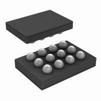
LM2758TL/NOPB National Semiconductor, LM2758TL/NOPB Datasheet - Page 3

LM2758TL/NOPB
Manufacturer Part Number
LM2758TL/NOPB
Description
IC LED DRIVER PHOTO FLASH 12USMD
Manufacturer
National Semiconductor
Series
PowerWise®r
Type
Photo Flash LEDr
Datasheet
1.LM2758TLNOPB.pdf
(14 pages)
Specifications of LM2758TL/NOPB
Constant Current
Yes
Topology
Switched Capacitor (Charge Pump)
Number Of Outputs
1
Internal Driver
Yes
Type - Primary
Flash/Torch
Frequency
800kHz ~ 1.5MHz
Voltage - Supply
2.7 V ~ 5.5 V
Voltage - Output
2.7 V ~ 5.3 V
Mounting Type
Surface Mount
Package / Case
12-MicroSMD
Operating Temperature
-40°C ~ 85°C
Current - Output / Channel
700mA
Internal Switch(s)
Yes
Efficiency
90%
Lead Free Status / RoHS Status
Lead free / RoHS Compliant
Other names
LM2758TL
LM2758TL
LM2758TLTR
LM2758TL
LM2758TLTR
I
V
I
I
V
V
R
F
I
I
T
V
V
LED
D
LED-IND
Q
SD
Symbol
SW
OUT
SET
GDX
OUT
IH
IL
OUT
/I
Absolute Maximum Ratings
2)
If Military/Aerospace specified devices are required,
please contact the National Semiconductor Sales Office/
Distributors for availability and specifications.
ESD Caution Notice
National Semiconductor recommends that all integrated circuits be handled with appropriate ESD precautions. Failure to observe
proper ESD handling techniques can result in damage to the device.
Electrical Characteristics
Limits in standard typeface are for T
C
V
V
EN1, EN2 pins: Voltage to GND
Continuous Power Dissipation
(Note
Junction Temperature (T
Storage Temperature Range
Maximum Lead Temp. (Soldering)
ESD Ratings
SET
EN1
≤
IN
Human Body Model
Machine Model
, CP
T
= V
J
3)
≤
OUT
IN
+125 °C). Unless otherwise noted, specifications apply to the LM2758 Typical Application Circuit (pg.1) with V
LED Current Accuracy
I
LED Current to Set Current
Ratio
Indicator Current Level
1x to 1.5x Gain Transition
Voltage Threshold on
V
Output Voltage
1x Mode Output
Impedance
1.5x Mode Output
Impedance
Switching Frequency
Quiescent Current
Shutdown Current
Time-out Duration
Input Logic High
Input Logic Low
, V
SET
LED
pins: Voltage to GND
EN2
Pin Voltage
(Note
-
= 0V, C1 = C2 = 1 µF, C
Parameter
4)
J-MAX
)
J
= 25°C. Limits in boldface type apply over the full operating junction temperature range (-40°
I
Flash Mode
Torch Mode
Indicator Mode
32 kHZ PWM Mode
I
1x Mode, I
1.5x Mode, I
I
I
I
I
Device Disabled
(Note
Pins: EN1, EN2
Pins: EN1, EN2
LED
OUT
OUT
OUT
OUT
OUT
-0.3V to (V
IN
= 500 mA, Flash Mode
= 500 mA
= 200 mA, V
= 500 mA, V
= 0 mA 1x Mode
= 0 mA 1.5x Mode
Internally Limited
= C
13)
-65°C to 150°C
-0.3V to 6.0V
w/ 6.0V max
(Note
(Note
OUT
OUT
IN
OUT
(Note
= 2.2 µF, R
+ 0.3V)
= 0 mA
1,
150°C
2,
200V
= 0 mA
Conditions
(Note
IN
IN
Note
2kV
Note
= 3.3V
= 3.3V
5)
12)
8)
(Note
SET
3
(Note
= 20 kΩ
Operating Ratings
Thermal Information
10)
Input Voltage Range
Junction Temperature Range (T
Ambient Temperature Range (T
(Note
Junction-to-Ambient Thermal Resistance
Resistance (θ
(Note
11)
(Note
6)
7)
9).
JA
), micro SMD package
Min
450
640
0.8
1.2
1/32 x
TORCH
7650
1639
0.33
1.25
0.01
I
Typ
500
300
814
1.3
V
4.8
1.5
0.7
LED-
4
A
(Note
J
IN
)
)
1,
Note
1000
-40°C to +125°C
Max
0.53
550
-40°C to +85 °C
5.3
2.0
1.5
0.8
0.4
5
1
2)
2.7V to 5.5V
www.national.com
IN
56°C/W
= 3.6V,
Units
msec
MHz
mA
mA
mV
mA
µA
V
V
Ω
V
V


