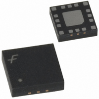
FAN5607HMPX Fairchild Semiconductor, FAN5607HMPX Datasheet - Page 8

FAN5607HMPX
Manufacturer Part Number
FAN5607HMPX
Description
IC LED DRIVR WHITE BCKLGT 16-MLP
Manufacturer
Fairchild Semiconductor
Type
Backlight, White LEDr
Datasheet
1.FAN5607HMPX.pdf
(13 pages)
Specifications of FAN5607HMPX
Topology
PWM, Switched Capacitor (Charge Pump)
Number Of Outputs
4
Internal Driver
Yes
Type - Primary
Backlight
Type - Secondary
White LED
Frequency
800kHz ~ 1.2MHz
Voltage - Supply
2.4 V ~ 5.5 V
Voltage - Output
3.62V
Mounting Type
Surface Mount
Package / Case
16-MLP
Operating Temperature
-40°C ~ 85°C
Current - Output / Channel
30mA
Internal Switch(s)
Yes
Efficiency
93%
Number Of Segments
4
Operating Supply Voltage
2.4 V to 5.5 V
Maximum Operating Temperature
+ 85 C
Mounting Style
SMD/SMT
Minimum Operating Temperature
- 40 C
Lead Free Status / RoHS Status
Lead free / RoHS Compliant
Other names
FAN5607HMPXTR
FAN5607HMPX_NL
FAN5607HMPX_NLTR
FAN5607HMPX_NLTR
FAN5607HMPX_NL
FAN5607HMPX_NLTR
FAN5607HMPX_NLTR
Available stocks
Company
Part Number
Manufacturer
Quantity
Price
Part Number:
FAN5607HMPX
Manufacturer:
FAIRCHILD/ن»™ç«¥
Quantity:
20 000
Block Diagram
FAN5607
Circuit Description
The FAN5607’s switched capacitor DC/DC converter auto-
matically configures its internal switches to achieve high
efficiency and to provide tightly regulated output currents for
the LEDs. An analog detector determines which diode
requires the highest voltage in order to sustain the pre-set
current levels, and adjusts the pump regulator accordingly.
Every diode has its own linear current regulator. In addition,
a voltage regulator controls the output voltage when the bat-
tery voltage is within a range where linear regulation can
provide maximum possible efficiency. If the battery voltage
is too low to sustain the diode current in the linear mode, a
fractional 3:2 charge pump is enabled. When the battery
voltage drops further and this mode is no longer sufficient to
sustain proper operation, the pump is automatically reconfig-
ured to operate in 2:1 mode. As the battery discharges and
8
EN
GND
V
R
IN
SET
Mode Change
Current Range
On Off
And
Ref1
V
Regulator
IN
Linear
Ref4 (BG)
Bandgap
Reference
Range Selection
Low Battery Ref.
Oscillator
Regulator
Ref3
Reference
Voltage
Selector
Figure 2. Block Diagram
D
R
I
V
E
R
S
the voltage decays, the FAN5607 switches between modes to
maintain a constant current through LED throughout the bat-
tery life. The transition has hysteresis to prevent toggling.
Supply Voltage
The internal supply voltage for the device is automatically
selected from V
Soft Start
The soft-start circuit limits inrush current when the device is
initially powered up and enabled. The reference voltage con-
trols the rate of the output voltage ramp-up to its final value.
Typical start-up time is 0.4ms. The rate of the output voltage
ramp-up is controlled by an internally generated slow ramp,
and an internal variable resistor limits the input current.
P
U
M
P
1µF
1µF
Ref2
IN
Power
Good
Analog
Detector
or V
OUT
pins, whichever is higher.
5µF
PRODUCT SPECIFICATION
V
OUT
REV. 1.0.1 12/2/04


