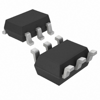
LT1937ESC6#TRM Linear Technology, LT1937ESC6#TRM Datasheet - Page 6

LT1937ESC6#TRM
Manufacturer Part Number
LT1937ESC6#TRM
Description
IC LED DRVR WHITE BCKLGT SC-70-6
Manufacturer
Linear Technology
Type
Backlight, White LEDr
Datasheet
1.LT1937ES5TRMPBF.pdf
(12 pages)
Specifications of LT1937ESC6#TRM
Constant Current
Yes
Topology
PWM, Step-Up (Boost)
Number Of Outputs
1
Internal Driver
Yes
Type - Primary
Backlight
Type - Secondary
White LED
Frequency
800kHz ~ 1.6MHz
Voltage - Supply
2.5 V ~ 10 V
Voltage - Output
36V
Mounting Type
Surface Mount
Package / Case
SC-70-6, SC-88, SOT-363
Operating Temperature
-40°C ~ 85°C
Internal Switch(s)
Yes
Efficiency
84%
Lead Free Status / RoHS Status
Contains lead / RoHS non-compliant
Current - Output / Channel
-
Other names
LT1937ESC6
LT1937ESC6
LT1937ESC6
Available stocks
Company
Part Number
Manufacturer
Quantity
Price
APPLICATIO S I FOR ATIO
LED Current Control
The LED current is controlled by the feedback resistor (R1
in Figure 1). The feedback reference is 95mV. The LED
current is 95mV/R1. In order to have accurate LED current,
precision resistors are preferred (1% is recommended).
The formula and table for R1 selection are shown below.
Table 4. R1 Resistor Value Selection
Open-Circuit Protection
In the cases of output open circuit, when the LEDs are
disconnected from the circuit or the LEDs fail, the feed-
back voltage will be zero. The LT1937 will then switch at
a high duty cycle resulting in a high output voltage, which
may cause the SW pin voltage to exceed its maximum 36V
rating. A zener diode can be used at the output to limit the
voltage on the SW pin (Figure 5). The zener voltage should
be larger than the maximum forward voltage of the LED
string. The current rating of the zener should be larger than
0.1mA.
LT1937
6
R1 = 95mV/I
V
IN
Figure 5. LED Driver with Open-Circuit Protection
I
LED
C
1 F
IN
10
12
15
20
5
(mA)
LED
V
SHDN
IN
U
LT1937
22 H
GND
L
U
SW
FB
D
W
R2
1k
R1 ( )
R1
6.34
19.1
9.53
7.87
6.34
4.75
U
1937 F05
C
0.22 F
OUT
(1)
Dimming Control
There are four different types of dimming control circuits:
1. Using a PWM Signal to SHDN Pin
With the PWM signal applied to the SHDN pin, the LT1937
is turned on or off by the PWM signal. The LEDs operate
at either zero or full current. The average LED current
increases proportionally with the duty cycle of the PWM
signal. A 0% duty cycle will turn off the LT1937 and
corresponds to zero LED current. A 100% duty cycle
corresponds to full current. The typical frequency range of
the PWM signal is 1kHz to 10kHz. The magnitude of the
PWM signal should be higher than the minimum SHDN
voltage high. The switching waveforms of the SHDN pin
PWM control are shown in Figures 6a and 6b.
100mV/DIV
100mV/DIV
Figure 6. PWM Dimming Control Using the SHDN Pin
2V/DIV
2V/DIV
SHDN
SHDN
FB
FB
(6b) 10kHz
(6a) 1kHz
200 s/DIV
20 s/DIV
LT1937
SHDN
PWM
1937 F06b
1937 F06a
1937f


