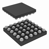
LP55281TLX/NOPB National Semiconductor, LP55281TLX/NOPB Datasheet - Page 13

LP55281TLX/NOPB
Manufacturer Part Number
LP55281TLX/NOPB
Description
IC LED DRIVER RGB 36-USMD
Manufacturer
National Semiconductor
Series
PowerWise®r
Type
RGB LED Driverr
Datasheet
1.LP55281RLNOPB.pdf
(28 pages)
Specifications of LP55281TLX/NOPB
Constant Current
Yes
Topology
PWM, Step-Up (Boost)
Number Of Outputs
12
Internal Driver
Yes
Type - Primary
Light Management Unit (LMU)
Type - Secondary
Color, RGB
Frequency
1MHz ~ 2MHz
Voltage - Supply
3 V ~ 5.5 V
Voltage - Output
4 V ~ 5.3 V
Mounting Type
Surface Mount
Package / Case
36-MicroSMD
Operating Temperature
-30°C ~ 85°C
Current - Output / Channel
300mA
Internal Switch(s)
Yes
Efficiency
88%
For Use With
LP55281RLEV - BOARD EVAL FOR LP5528 RGB DRIVER
Lead Free Status / RoHS Status
Lead free / RoHS Compliant
Other names
LP55281TLX
Functionality of RGB LED Outputs
(R1-4, G1-4, B1-4)
LP55281 has 4 sets of RGB/color LED outputs. Each set has
3 outputs, which can be controlled individually with a 6-bit
PWM control register. The pulsed current level for each LED
output is set with a single external resistor R
coarse adjustment bit for each LED output (see tables below).
Timing Diagram
Gx_PWM[5:0] /
Rx_PWM[5:0] /
Bx_PWM[5:0]
000 000
000 001
000 010
Rx_IPLS[7:6] /
Gx_IPLS[7:6] /
Bx_IPLS[7:6]
...
00
01
10
11
Awerage Sink
1/63*I
2/63*I
Current
...
0
PLS
PLS
(I
Sink Current Pulse
MAX
= 100*1.23/R
0.25*I
0.50*I
0.75*I
1.00*I
Pulse Ratio, %
I
PLS
RGB
MAX
MAX
MAX
MAX
1.6
3.2
...
and a 2-bit
0
RGB
)
13
Each RGB set must be enabled separately by setting EN_RG-
Bx bit to '1'. Note, that the device must be enabled (NSTBY =
'1') before the RGB outputs can be activated.
When any of EN_RGBx bits are set to '1' and NSTBY = '1',
the RGB driver takes a certain quiescent current from battery
even if all PWM control bits are '0'. The quiescent current is
dependent on R
mula I
PWM CONTROL TIMING
PWM frequency can be selected from 3 predefined values:
10 kHz, 20 kHz and 40 kHz. The frequency is selected with
FPWM1 and FPWM0 bits, see following table:
Each RGB set has equivalent internal PWM timing between
R, G and B: R has a fixed start time, G has a fixed midpulse
time and B has a fixed pulse end time. PWM start time for
each RGB set is different in order to minimize the instanta-
neous current loading due to the current sink switch on tran-
sition. See following timing diagram for details.
FPWM1
111 110
111 111
R_RGB
0
0
1
1
= 1.23V/R
RGB
FPWM0
resistor, and can be calculated from for-
RGB
0
1
0
1
62/63*I
63/63*I
20201117
.
PLS
PLS
PWM Frequency (f
19.84 kHz
39.68 kHz
39.68 kHz
9.92 kHz
98.4
100
www.national.com
PWM
)


