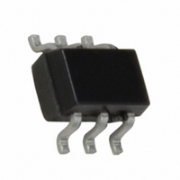
FAN5611S7X Fairchild Semiconductor, FAN5611S7X Datasheet - Page 8

FAN5611S7X
Manufacturer Part Number
FAN5611S7X
Description
IC LED DRIVER LINEAR SC-70-6
Manufacturer
Fairchild Semiconductor
Type
Linear (Non-Switching)r
Datasheet
1.FAN5611MPX.pdf
(14 pages)
Specifications of FAN5611S7X
Topology
Linear (LDO), PWM
Number Of Outputs
4
Internal Driver
Yes
Type - Primary
Backlight
Type - Secondary
Color, White LED
Voltage - Supply
3.3 V ~ 5.5 V
Mounting Type
Surface Mount
Package / Case
SC-70-6, SC-88, SOT-363
Operating Temperature
-40°C ~ 85°C
Current - Output / Channel
40mA
Efficiency
90%
Number Of Segments
4
Operating Supply Voltage
0.3 V to 1 V
Maximum Supply Current
20 mA
Maximum Power Dissipation
700 mW
Maximum Operating Temperature
+ 85 C
Mounting Style
SMD/SMT
Minimum Operating Temperature
- 40 C
Lead Free Status / RoHS Status
Lead free / RoHS Compliant
Voltage - Output
-
Frequency
-
Internal Switch(s)
-
Lead Free Status / Rohs Status
Details
Other names
FAN5611S7XTR
FAN5611S7X_NL
FAN5611S7X_NLTR
FAN5611S7X_NLTR
FAN5611S7X_NL
FAN5611S7X_NLTR
FAN5611S7X_NLTR
Available stocks
Company
Part Number
Manufacturer
Quantity
Price
Company:
Part Number:
FAN5611S7X
Manufacturer:
ISSI
Quantity:
15
Company:
Part Number:
FAN5611S7X
Manufacturer:
Fairchild Semiconductor
Quantity:
135
FAN5611/FAN5612/FAN5613/FAN5614 Rev. 1.0.9
© 2003 Fairchild Semiconductor Corporation
Application Information
Operational Descripton
The regulated current through each LED is a multiplica-
tion of the I
the R
I
Reference Figure 4, the I
mate V
to the formula:
R
For example, with V
through the LED results in I
to an approximate value of 1.2V for V
ure 4. The resulting R
ulation is 36kΩ.
The LED intensity can be adjusted by varying the duty
cycle of a square wave applied to the enable pin. Fre-
quency greater than 100Hz is best to avoid a "flickering"
effect. The maximum operation frequency is 10MHz.
Efficiency Considerations
The FAN561X driver’s low-dropout architecture can sig-
nificantly improve the efficiency compared to using sim-
ple ballast resistors. The system efficiency, defined as
the ratio between the LEDs’ power and the input sup-
plied power, can be calculated as:
The lower the V
ciency. Efficiency can be further improved by using a
higher V
Application Notes
The ultra-low voltage drop across the FAN561X series of
LED drivers allows the devices to drive white, blue, and
other color LEDs in a wide range of input voltages. The
driver can be used in many applications. Although only
the FAN5613 is shown in all three examples, any of the
FAN561X-series LED drivers can be used in the applica-
tions presented, due to their similar operation.
Example 1: Drive low V
from single cell Li-ion
When using white or blue low V
drivers low voltage drop, only 3.4V in V
the full 20mA LED current. At 3.1V, there is 5mA typical
current available for the LEDs. The single cell Li-ion is
utilized in applications like cell phones or digital still cam-
eras. In most cases, the Li-ion battery voltage level only
goes down to 3.0V voltage level, not down to the full dis-
charge level (2.7V) before requesting the charger.
Efficiency
SET
SET
= I
SET
= (V
LED
CTRL
IN
value. The I
CONTROL
with more LEDs, as shown in Example 3.
/ Current Gain
SET
. The value of R
=
(
current. The I
V
IN
CATHODE
- V
–
CONTROL
SET
V
SET
CTRL
CATHODE
F
value that maintains 10mA reg-
value can be calculated as:
, the higher the system effi-
SET
) / I
white or blue LEDs directly
SET
SET
SET
= 3V, a 10mA current limit
SET
vs. V
F
= 50µA. That translates
) V
is calculated according
value is determined by
LEDs, and utilizing the
⁄
CTRL
IN
CTRL
IN
, shown in Fig-
graph, to esti-
is needed for
8
where V
Key advantages:
• No boost circuit is needed for the LCD or keyboard
• Drivers are directly connected to a Li-ion battery.
• No EMI, no switching noise, no boost efficiency lost,
Example 2: Drive high V
existing bus from 4.0V to 5.5V
High V
the range of 3.2V to 4.0V. Driving these LEDs with the
maximum current of 20mA for maximum brightness,
usually requires a boost circuit for a single cell Li-ion
voltage range. In some cases, there is already a voltage
bus in the system, which can be utilized. Due to the ultra-
low voltage drop of the FAN561X series of LED drivers to
drive high-V
only 300mV higher than the highest V
where V
Key advantages:
• No boost circuit is needed for LCD or keyboard
• Driver utilizes the existing bus.
• Ultra-low voltage drop provides the full 20mA LED
V
backlight.
no capacitor, and no inductor.
backlight.
current at the lowest possible voltage level.
CONTROL
– V
– V
– V
– V
– V
– V
– V
– V
F
DROP
F (at 20mA)
IN (at 20mA)
IN (at 5mA Typical)
DROP
F (at 20mA)
IN (at 20mA)
IN (at 5mA Typical)
IN
white or blue LEDs have forward voltage drop in
IN
ENABLE
V
= Single cell Li-ion voltage.
= existing bus = 3.3V to 4.3V.
IN
F
R
< 0.3V
< 0.3V
I
SET
SET
white or blue LEDs, the V
< 3.1V (Low V
< 3.3V to 4.0V (High V
=V
=V
DROP
DROP
CTRL
ON/OFF
I4
~ 3.1V
~ 3.3V
+ V
+ V
F
white or blue LEDs from
F
F
I3
FAN5613
F
= 3.4V
= 3.6V to 4.3V
)
GND
F
I2
in the circuit.
F
)
IN
www.fairchildsemi.com
needs to be
I1


