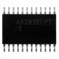
A6282ELP-T Allegro Microsystems Inc, A6282ELP-T Datasheet - Page 6

A6282ELP-T
Manufacturer Part Number
A6282ELP-T
Description
IC LED DRIVER LINEAR 24-TSSOP
Manufacturer
Allegro Microsystems Inc
Type
Linear (Non-Switching)r
Datasheet
1.A6282ELPTR-T.pdf
(13 pages)
Specifications of A6282ELP-T
Constant Current
Yes
Number Of Outputs
16
Internal Driver
Yes
Type - Primary
Backlight
Type - Secondary
Color, White LED
Frequency
30MHz
Voltage - Supply
3 V ~ 5.5 V
Voltage - Output
12V
Mounting Type
Surface Mount
Package / Case
24-TSSOP Exposed Pad, 24-eTSSOP, 24-HTSSOP
Operating Temperature
-40°C ~ 85°C
Current - Output / Channel
50mA
Internal Switch(s)
Yes
Lead Free Status / RoHS Status
Lead free / RoHS Compliant
Efficiency
-
Topology
-
Other names
620-1222-5
A6282
SWITCHING CHARACTERISTICS
R
ELECTRICAL CHARACTERISTICS (continued),
Thermal Shutdown Temperature
Thermal Shutdown Hysteresis
Reference Voltage at External
Resistor REXT
1
2
individual units, within the specified maximum and minimum limits.
3
difference from I
4
Clock Frequency
Clock Frequency (cascaded devices)
Clock Pulse Duration
LE Pulse Duration
Setup Time
Hold Time
Rise Time
Fall Time
Propagation Delay Time
Output Enable Pulse Duration
1
2
individual units, within the specified maximum and minimum limits.
Tested at 25°C. Specifications are assured by design and characterization over the operating temperature range of –40°C to 85°C.
Typical data are for initial design estimations only, and assume optimum manufacturing and application conditions. Performance may vary for
Err = (I
Recommended operating range: V
Tested at 25°C. Specifications are assured by design and characterization over the operating temperature range of –40°C to 85°C.
Typical data are for initial design estimations only, and assume optimum manufacturing and application conditions. Performance may vary for
L
= 51 Ω, C
O
(min or max) – I
Characteristic
Characteristic
L
= 15 pF (see also Timing Diagrams section)
O
(av).
O
(av)) / I
(A) Circuit for t
O
(av). I
O
A6282
= 1.0 to 3.0 V.
O
Symbol
(av) is the average current of all outputs. I
t
f
w(OE)
f
CLKC
t
t
t
t
t
t
t
Symbol
T
CLK
wh0
wh1
t
t
at T
su0
su1
t
t
t
t
pd0
pd1
pd2
h0
h1
r0
r1
f0
f1
T
JTSDhys
V
JTSD
Parameter Measurement Circuits
EXT
f0
A
1
, t
= 25°C, V
pd0
CLK
CLK
CLK = high
LE = high
SDI to CLK↑
CLK↑ to LE↑
CLK↑ to SDI
LE↓ to CLK↑
SDO, 10/90% points (measurement circuit A)
OUTx, V
SDO, 10/90% points (measurement circuit A)
OUTx, V
CLK↑ to SDO↑↓ (measurement circuit A)
¯ O ¯ ¯ ¯ E ¯ ↓ to OUTx↑↓ (measurement circuit B)
LE↑ to OUTx↑↓ (measurement circuit B)
(see Timing Diagrams section)
Temperature increasing
R
, and t
EXT
SDO
DD
DD
= 374
16-Channel Constant-Current LED Driver
DD
r0
at T
= 5 V,10/90% points (measurement circuit B)
= 5 V,10/90% points (measurement circuit B)
= V
15 pF
A
1
Test Conditions
IH
= 25°C, V
Test Conditions
= 5.0 V, V
(B) Circuit for t
DD
A6282
DS
O
= 3.0 to 5.5 V, unless otherwise noted
(min or max) is the output current with the greatest
= 1 V, V
f1
, t
IL
pd1
= 0 V, R
, t
pd2
OUTx
, and t
Min.
EXT
–
–
–
115 Northeast Cutoff
1.508.853.5000; www.allegromicro.com
Allegro MicroSystems, Inc.
Worcester, Massachusetts 01615-0036 U.S.A.
V
= 910 Ω, I
r1
L
Min.
16
20
10
10
10
10
60
.
–
–
–
–
–
–
–
–
–
R
C
Typ.
1.21
L
L
165
15
O
Typ.
2
10
10
= 21.4 mA, V
–
–
–
–
–
–
–
–
–
–
–
–
–
–
2
Max.
–
–
–
Max.
30
25
16
30
16
30
30
60
60
–
–
–
–
–
–
–
L
= 2 V,
Unit
°C
°C
MHz
MHz
Unit
V
ns
ns
ns
ns
ns
ns
ns
ns
ns
ns
ns
ns
ns
ns
6


