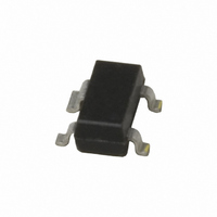
MIC5018YM4 TR Micrel Inc, MIC5018YM4 TR Datasheet - Page 3

MIC5018YM4 TR
Manufacturer Part Number
MIC5018YM4 TR
Description
IC DRIVER MOSFET HI SIDE SOT143
Manufacturer
Micrel Inc
Series
IttyBitty®r
Datasheet
1.MIC5018YM4_TR.pdf
(8 pages)
Specifications of MIC5018YM4 TR
Configuration
High-Side
Input Type
Non-Inverting
Delay Time
750µs
Number Of Configurations
1
Number Of Outputs
1
Voltage - Supply
2.7 V ~ 9 V
Operating Temperature
-40°C ~ 85°C
Mounting Type
Surface Mount
Package / Case
SOT-143, SOT-143B, TO-253AA
Number Of Drivers
1
Driver Configuration
Non-Inverting
Driver Type
High Side
Input Logic Level
TTL
Operating Supply Voltage (max)
9V
Operating Supply Voltage (min)
2.7V
Turn Off Delay Time
30us
Turn On Delay Time (max)
2.1ms
Operating Temp Range
-40C to 85C
Operating Temperature Classification
Industrial
Mounting
Surface Mount
Pin Count
3 +Tab
Lead Free Status / RoHS Status
Lead free / RoHS Compliant
Current - Peak
-
High Side Voltage - Max (bootstrap)
-
Lead Free Status / Rohs Status
Compliant
Other names
576-1238-2
Absolute Maximum Ratings
Supply Input Voltage (V
Control Voltage (V
Gate Voltage (V
Ambient Temperature Range (T
Electrical Characteristics
Test Circuit
Micrel, Inc.
Parameter
Supply Current
Control Input Voltage
Control Input Current
Control Input Capacitance
Zener Diode Output Clamp
Gate Output Voltage
Gate Output Current
Gate Turn-On Time
Gate Turn-Off Time
April 2006
Notes:
General Note: Devices are ESD protected, however handling precautions are recommended.
1. Typical values at T
2. Guaranteed by design.
3. Resistive load selected for V
4. Turn-on time is the time required for gate voltage to rise to 4V greater than the supply voltage. This represents a typical MOSFET gate threshold
5. Turn-off time is the time required for the gate voltage to fall to 4V above the supply voltage. This represents a typical MOSFET gate threshold
voltage.
voltage.
G
).........................................................+16V
CTL
A
) ................................... –0.6V to +16V
= 25°C. Minimum and maximum values indicate performance at –40°C ≥ T
SUPPLY
OUT
) .....................................+10V
= 10V.
A
)...............–40°C to +85°C
Conditions
V
V
2.7V ≤ V
2.7V ≤ V
5V ≤ V
2.7V ≤ V
(2)
V
V
V
V
V
V
V
SUPPLY
SUPPLY
SUPPLY
SUPPLY
SUPPLY
SUPPLY
SUPPLY
SUPPLY
SUPPLY
0.1µF
5V
0V
SUPPLY
V
= 3.3V
= 5V
= 9V
= 2.7V
= 3.0V
= 4.5V
= 5V
= 4.5V
= 4.5V
S U P P L Y
SUPPLY
SUPPLY
SUPPLY
2
4
(1)
≤ 9V
V S
C T L
≤ 9V
≤ 5V
≤ 9V
MIC5018
GND
3
Operating Ratings
Lead Temperature, soldering 10 sec ..........................300ºC
Package Thermal Resistance
G
SOT-143
SOT-143
1
3
V
C
C
V
V
V
C
C
V
V
V
V
CTL
CTL
CTL
OUT
L
L
CTL
CTL
CTL
L
L
CTL
= 3000pF
= 3000pF
= 1000pF
= 1000pF
= 3.3V
= 0V
= 0V
for logic 0 input
for logic 1 input
for logic 1 input
= 10V
= 5V
C
(θ
(θ
L
JA
JC
(3)
V
(4)
(5)
) ....................................................220°C/W
) ....................................................130°C/W
(4)
(5)
OU T
A
≥ +85°C. Parts production tested at 25°C.
11.4
Min
2.0
2.4
6.3
7.1
13
0
Typ
0.01
0.01
13.4
0.75
150
7.1
8.2
9.5
2.1
70
16
10
30
0
5
(408) 955-1690
M9999-042406
V
V
Max
SUPPLY
SUPPLY
140
300
0.8
1.5
4.2
19
20
60
1
1
1
MIC5018
Units
Ms
ms
µA
µA
µA
µA
µA
pF
µA
µs
µs
V
V
V
V
V
V
V


