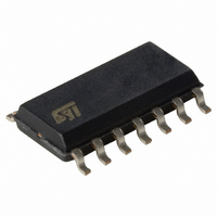
L6386ED013TR STMicroelectronics, L6386ED013TR Datasheet - Page 3

L6386ED013TR
Manufacturer Part Number
L6386ED013TR
Description
IC DRIVER HI/LO SIDE HV 14-SOIC
Manufacturer
STMicroelectronics
Type
High Side/Low Sider
Datasheet
1.L6386ED013TR.pdf
(18 pages)
Specifications of L6386ED013TR
Configuration
High and Low Side, Independent
Input Type
Non-Inverting
Delay Time
110ns
Current - Peak
400mA
Number Of Configurations
1
Number Of Outputs
2
High Side Voltage - Max (bootstrap)
600V
Voltage - Supply
17V
Operating Temperature
-40°C ~ 125°C
Mounting Type
Surface Mount
Package / Case
14-SOIC (3.9mm Width), 14-SOL
Product
H-Bridge Drivers
Rise Time
50 ns
Fall Time
30 ns
Maximum Power Dissipation
750 mW
Maximum Operating Temperature
+ 125 C
Mounting Style
SMD/SMT
Bridge Type
Half Bridge
Minimum Operating Temperature
- 45 C
Number Of Drivers
2
Driver Configuration
Non-Inverting
Driver Type
High and Low Side
Input Logic Level
CMOS/TTL
Propagation Delay Time
150ns
Frequency (max)
400KHz
Operating Supply Voltage (max)
17V
Peak Output Current
650mA
Power Dissipation
750mW
Turn Off Delay Time
150fs
Turn On Delay Time (max)
150ps
Operating Temp Range
-45C to 125C
Operating Temperature Classification
Automotive
Mounting
Surface Mount
Pin Count
14
Package Type
SO
For Use With
497-5492 - EVAL BOARD FOR L6384/L6385/L6386
Lead Free Status / RoHS Status
Lead free / RoHS Compliant
Other names
497-6216-2
Available stocks
Company
Part Number
Manufacturer
Quantity
Price
Company:
Part Number:
L6386ED013TR
Manufacturer:
MT
Quantity:
6 222
Part Number:
L6386ED013TR
Manufacturer:
ST
Quantity:
20 000
L6386E
1
1.1
Note:
1.2
1.3
Electrical data
Absolute maximum ratings
Table 1.
ESD immunity for pins 12, 13 and 14 is guaranteed up to 900 V (human body model)
Thermal data
Table 2.
Recommended operating conditions
Table 3.
1. If the condition Vboot - Vout < 18 V is guaranteed, Vout can range from -3 to 580 V
2. V
Symbol
Symbol
Symbol
V
dV
R
V
V
V
BS
V
V
f
V
V
V
T
P
V
T
th(JA)
sw
out
out
boot
V
BS
diag
T
cc
hvg
out
stg
J
lvg
cin
tot
cc
(2)
j
i
/dt
= V
boot
Pin
12
14
Thermal resistance junction to ambient
Output voltage
Supply voltage
Floating supply voltage
High side gate output voltage
Low side gate output voltage
Logic input voltage
Open drain forced voltage
Comparator input voltage
Allowed output slew rate
Total power dissipation (T
Junction temperature
Storage temperature
4
Absolute maximum ratings
Thermal data
Recommended operating conditions
- V
out
Output voltage
Floating supply voltage
Switching frequency
Supply voltage
Junction temperature
Parameter
Doc ID 13989 Rev 2
Parameter
Parameter
J
= 85 °C)
HVG,LVG load C
Test condition
L
= 1 nF
SO-14
Min
-45
165
-0.3 to V
-0.3 to V
-0.3 to V
-0.3 to V
(1)
(1)
-3 to V
- 0.3 to +18
- 1 to V
-50 to 150
-1 to 618
Value
750
150
50
boot
Typ
cc
cc
cc
cc
boot
DIP-14
+0.3
+0.3
+0.3
+0.3
- 18
100
Electrical data
Max
580
400
125
17
17
°C/W
V/ns
Unit
Unit
mW
Unit
°C
°C
kHz
V
V
V
V
V
V
V
V
°C
V
V
V
3/18


