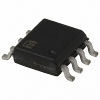
MIC5021YM Micrel Inc, MIC5021YM Datasheet - Page 4

MIC5021YM
Manufacturer Part Number
MIC5021YM
Description
IC DRIVER MOSF HI SIDE HS 8-SOIC
Manufacturer
Micrel Inc
Datasheet
1.MIC5021YM_TR.pdf
(10 pages)
Specifications of MIC5021YM
Configuration
High-Side
Input Type
Non-Inverting
Delay Time
500ns
Number Of Configurations
1
Number Of Outputs
1
Voltage - Supply
12 V ~ 36 V
Operating Temperature
-40°C ~ 85°C
Mounting Type
Surface Mount
Package / Case
8-SOIC (3.9mm Width)
Device Type
High Side
Module Configuration
High Side
Input Delay
500ns
Output Delay
800ns
Supply Voltage Range
12V To 36V
Driver Case Style
SOIC
No. Of Pins
8
Number Of Drivers
1
Driver Configuration
Non-Inverting
Driver Type
High Side
Input Logic Level
TTL
Rise Time
500ns
Fall Time
500ns
Frequency (max)
150MHz
Operating Supply Voltage (max)
36V
Operating Supply Voltage (min)
12V
Turn Off Delay Time
1.5ps
Turn On Delay Time (max)
1ns
Operating Temp Range
-40C to 85C
Operating Temperature Classification
Industrial
Mounting
Surface Mount
Pin Count
8
Lead Free Status / RoHS Status
Lead free / RoHS Compliant
Current - Peak
-
High Side Voltage - Max (bootstrap)
-
Lead Free Status / RoHS Status
Compliant, Lead free / RoHS Compliant
Other names
576-2354
MIC5021YM
MIC5021YM
Available stocks
Company
Part Number
Manufacturer
Quantity
Price
Company:
Part Number:
MIC5021YM
Manufacturer:
ROHM
Quantity:
7 167
Part Number:
MIC5021YM
Manufacturer:
MICREL/麦瑞
Quantity:
20 000
MIC5021
Typical Characteristics
MIC5021
Timing Diagram 2. Fault Condition, C
Differential
Sense +,–
1000
950
900
850
800
750
2.5
2.0
1.5
1.0
0.5
0.0
25
20
15
10
Cycle vs. Timing Capacitance
5
0
0.1
5
5
Overcurrent Retry Duty
NOT E:
t
INDEPENDENT
Input
ON
OF V
Gate
Gate Turn-On Delay vs.
INCLUDES PROPAGATION DELAY
10
10
Supply Current vs.
, t
1
Supply Voltage
OFF
Supply Voltage
SUPPLY
V
15
15
C
GATE
V
L
T I M E
15V (max.)
V
V
IN
= 1500pF (IRCZ34)
10
SUPPLY
SUPPLY
V
20
20
TTL (H)
C
Source
IN
= 0V
C
= V
T
50mV
BOOST
= 5V
V
(pF)
25
25
SUPPLY
100
0V
SUPPLY
0V
t
ON
(V)
(V)
= 0.01µF
30
30
= 5µs
1000 10000
= 12V
+ 10V
35
35
6µs
40
40
Sense +,–
Differential
20µs
Timing Diagram 1. Normal Operation
Input
Gate
T
= Open
15V (max.)
100
2.5
2.0
1.5
1.0
0.5
0.0
80
60
40
20
25
20
15
10
1x10
TTL (H)
0
Source
5
0
0
50mV
5
V
V
0
0V
Gate Turn-On Delay vs.
0V
GATE
SUPPLY
INCLUDES PROPAGATION DELAY
1x10
Gate Voltage Change
10
V
vs. Supply Voltage
G AT E
Gate Capacitance
5
Input Current vs.
= V
15
1
Input Voltage
= 12V
1x10
= V
C
V
SUPPLY
10
SUPPLY
GATE
20
V
G AT E
IN
4
2
V
1x10
(V)
25
(pF)
SUPPLY
15
+ 4V
– V
(V)
Differential
Sense +,–
3
Timing Diagram 3. Fault Condition, C
S U P P L Y
30
1x10
= 12V
20
35
4
Input
Gate
1x10
25
40
5
15V (max.)
TTL (H)
Source
50mV
0V
0V
2000
1750
1500
1250
1000
6µs
900
850
800
750
700
650
750
80
70
60
50
40
30
20
-60 -30
5
5
V
R
Gate Turn-Off Delay vs.
Gate Turn-On Dalay vs.
INCLUDES PROPAGATION DELAY
INCLUDES PROPAGATION DELAY
G AT E
L
10
10
Sense Threshold vs.
= 400
TEMPERATURE (°C)
Supply Voltage
Supply Voltage
= V
15
15
Temperature
C
V
0
L
GATE
V
V
SUPPLY
= 1500pF (IRCZ34)
SUPPLY
SUPPLY
20
20
C
(IRCZ34)
30
C
G AT E
BOOST
= V
25
25
60
+ 4V
SUPPLY
(V)
(V)
= 1500pF
T
= 0.01µF
30
30
90 120 150
= Grounded
+ 4V
35
35
Micrel, Inc.
July 2005
40
40


