IR2113-1PBF International Rectifier, IR2113-1PBF Datasheet - Page 6
IR2113-1PBF
Manufacturer Part Number
IR2113-1PBF
Description
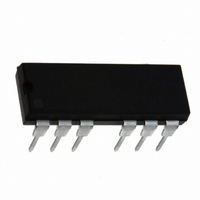
IC MOSFET DRVR HI/LO SIDE 14DIP
Manufacturer
International Rectifier
Datasheet
1.IR2113-1PBF.pdf
(18 pages)
Specifications of IR2113-1PBF
Configuration
High and Low Side, Independent
Input Type
Non-Inverting
Delay Time
120ns
Current - Peak
2.5A
Number Of Configurations
1
Number Of Outputs
2
High Side Voltage - Max (bootstrap)
600V
Voltage - Supply
10 V ~ 20 V
Operating Temperature
-40°C ~ 125°C
Mounting Type
Through Hole
Package / Case
14-DIP (0.300", 7.62mm), 13 Leads
Current, Output
2 A
Current, Output, Limiting
A
Delay, Propagation, Turn-off
125 ns
Delay, Propagation, Turn-on
150 ns
Package Type
PDIP
Power Dissipation
1.6 W
Temperature, Ambient, Maximum
+125 °
Temperature, Ambient, Minimum
–41 °
Temperature, Operating
-40 to +125 decC
Thermal Resistance, Junction To Ambient
75 °C/W
Time, Fall, Turn-off
25 ns
Time, Rise, Turn-on
35 ns
Transistor Type
MOSFET
Voltage, Offset
600 V
Voltage, Output
20 V
Voltage, Output, High Level
600 V
Voltage, Output, Low Level
0 V
Lead Free Status / RoHS Status
Lead free / RoHS Compliant
Other names
*IR2113-1PBF


IR2110(-1-2)(S)PbF/IR2113(-1-2)(S)PbF
HIN
6
LIN
SD
Figure 5. Shutdown Waveform Definitions
10
F
Figure 1. Input/Output Timing Diagram
Figure 3. Switching Time Test Circuit
0.1
SD
F
HO
LO
V
11
cc
12
10
13
9
=15V
3
2
50%
6
t sd
5
7
1
C L
C L
90%
0.1
F
LO
HO
10
F
(0 to 500V/600V)
10
F
15V
V B
+
-
V
S
Figure 2. Floating Supply Voltage Transient Test Circuit
10
F
HIN
LIN
HO
LO
Figure 6. Delay Matching Waveform Definitions
HIN
LIN
Figure 4. Switching Time Waveform Definition
0.1
F
V
t on
11
cc
12
10
13
9
=15V
MT
3
2
50%
50%
10KF6
10%
t r
LO
6
5
7
1
OUTPUT
MONITOR
90%
10%
HO
50%
0.1
F
HO
10KF6
50%
90%
IRF820
t off
200
90%
LO
H
HV = 10 to 500V/600V
10%
t f
10KF6
www.irf.com
HO
MT
dV S
dt
+
>50 V/ns
100 F
Related parts for IR2113-1PBF
Image
Part Number
Description
Manufacturer
Datasheet
Request
R

Part Number:
Description:
IC MOSFET DRVR HI/LO SIDE 14-DIP
Manufacturer:
International Rectifier
Datasheet:
Part Number:
Description:
IC MOSFET DRVR HI/LO SIDE 14-DIP
Manufacturer:
International Rectifier
Datasheet:
Part Number:
Description:
IC MOSFET DRVR HI/LO SIDE 16-DIP
Manufacturer:
International Rectifier
Datasheet:

Part Number:
Description:
IC MOSFET DRVR HI/LO SIDE 16DIP
Manufacturer:
International Rectifier
Datasheet:

Part Number:
Description:
SCHOTTKY RECTIFIER
Manufacturer:
International Rectifier Corp.
Datasheet:
Part Number:
Description:
SCHOTTKY RECTIFIER
Manufacturer:
International Rectifier Corp.
Datasheet:
Part Number:
Description:
SCHOTTKY RECTIFIER
Manufacturer:
International Rectifier Corp.
Datasheet:
Part Number:
Description:
SCHOTTKY RECTIFIER
Manufacturer:
International Rectifier Corp.
Datasheet:
Part Number:
Description:
SCHOTTKY RECTIFIER
Manufacturer:
International Rectifier Corp.
Datasheet:
Part Number:
Description:
SCHOTTKY RECTIFIER
Manufacturer:
International Rectifier Corp.
Datasheet:
Part Number:
Description:
SCHOTTKY RECTIFIER
Manufacturer:
International Rectifier Corp.
Datasheet:
Part Number:
Description:
SCHOTTKY RECTIFIER
Manufacturer:
International Rectifier Corp.
Datasheet:
Part Number:
Description:
SCHOTTKY RECTIFIER
Manufacturer:
International Rectifier Corp.
Datasheet:
Part Number:
Description:
SCHOTTKY RECTIFIER
Manufacturer:
International Rectifier Corp.
Datasheet:
Part Number:
Description:
SCHOTTKY RECTIFIER
Manufacturer:
International Rectifier Corp.
Datasheet: