NCP5181PG ON Semiconductor, NCP5181PG Datasheet - Page 4
NCP5181PG
Manufacturer Part Number
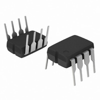
NCP5181PG
Description
IC MOSFET DRVR HIGH VOLT 8-DIP
Manufacturer
ON Semiconductor
Type
High Side/Low Sider
Datasheet
1.NCP5181PG.pdf
(12 pages)
Specifications of NCP5181PG
Configuration
Half Bridge
Input Type
Non-Inverting
Delay Time
100ns
Current - Peak
1.4A
Number Of Configurations
1
Number Of Outputs
2
High Side Voltage - Max (bootstrap)
600V
Voltage - Supply
10 V ~ 20 V
Operating Temperature
-40°C ~ 125°C
Mounting Type
Through Hole
Package / Case
8-DIP (0.300", 7.62mm)
Rise Time
60 ns
Fall Time
40 ns
Supply Voltage (min)
10 V
Supply Current
6.5 mA
Maximum Power Dissipation
100 mW
Maximum Operating Temperature
+ 150 C
Mounting Style
Through Hole
Bridge Type
Full Bridge, Half Bridge
Minimum Operating Temperature
- 55 C
Number Of Drivers
2
Lead Free Status / RoHS Status
Lead free / RoHS Compliant
Available stocks
Company
Part Number
Manufacturer
Quantity
Price
Company:

Part Number:
NCP5181PG
Manufacturer:
ON
Quantity:
4 660
Part Number:
NCP5181PG
Manufacturer:
ON/安森美
Quantity:
20 000


*Note: see also characterization curves
1. Guaranteed by design.
2. Turn--off propagation delay @ V
3. See characterization curve for Δ
4. Timing diagram definition see Figures 4, 5 and 6.
ELECTRICAL CHARACTERISTICS
OUTPUT SECTION
Output High Short Circuit pulsed Current
V
Output Low Short Circuit Pulsed Current
V
Output Resistor (Typical Value @ 25C Only)
Source
Output Resistor (Typical Value @ 25C Only)
Sink
DYNAMIC OUTPUT SECTION
Turn--on Propagation Delay (V
Turn--off Propagation Delay (V
Output Voltage Risetime
(from 10% to 90% @ V
Output Voltage Falling Edge
(from 90% to 10% @ V
Propagation Delay Matching between the High Side and the Low Side
@ 25C (Note 3)
Minimum Input Pulse Width that Changes the Output
INPUT SECTION
Low Level Input Voltage Threshold
Input Pulldown Resistor (V
High Level Input Voltage Threshold
SUPPLY SECTION
V
V
Hysteresis on V
V
(V
V
Hysteresis on V
Leakage Current on High Voltage Pins to GND
(V
Consumption in Active Mode
(V
Consumption in Inhibition Mode (V
V
V
DRV
DRV
CC
CC
boot
boot
CC
boot
boot_stup
BOOT
CC
UV Startup Voltage Threshold
UV Shutdown Voltage Threshold
Current Consumption in Inhibition Mode
= V
Startup Voltage Threshold Reference to Bridge Pin
UV Shutdown Voltage Threshold
Current Consumption in Inhibition Mode
= 0 V, PW 10 ms, (Note 1)
= V
= V
boot
CC
= V
BRIDGE
, PW 10 ms, (Note 1)
, f
boot
sw
CC
boot
= 100 kHz and 1 nF Load on Both Driver Outputs)
-- V
= DRV_HI = 600 V)
bridge
CC
CC
= 15 V) with 1 nF Load
= 15 V) with 1 nF Load
IN
)
< 0.5 V)
bridge
bridge
Rating
Rating
bridge
CC
t
parameters variation on the full range temperature.
= 0 V)
= 0 V or 50 V) (Note 2)
= V
= 600 V is guaranteed by design
(V
boot
CC
)
= V
boot
= 15 V, V
http://onsemi.com
gnd
= V
4
bridge
V
V
V
, --40C < T
V
V
boot_shtdwn
boot_shtdwn
I
V
Symbol
I
Symbol
CC_shtdwn
HV_LEAK
I
DRVhigh
boot_stup
DRVlow
CC_stup
CC_hyst
R
t
I
I
I
I
R
t
t
V
R
V
OFF
CC1
CC2
CC3
CC4
PW
ON
Δ
t
OH
t
OL
IN
IN
r
f
IN
t
A
< 125C, Outputs loaded with 1 nF)
Min
Min
2.3
7.9
7.3
0.3
7.9
7.3
0.3
--
--
--
--
--
--
--
--
--
--
--
--
--
--
--
--
--
T
A
- -40C to 125C
Typ
Typ
100
100
200
250
215
1.4
2.2
8.9
8.2
0.7
8.9
8.2
0.7
0.5
4.5
40
20
20
35
5
2
--
--
--
Max
Max
170
170
100
400
0.8
9.8
9.0
9.8
9.0
6.5
12
60
40
35
40
8
--
--
--
--
--
--
--
--
Units
Units
mA
kΩ
mA
mA
mA
mA
ns
ns
ns
ns
ns
ns
Ω
Ω
A
A
V
V
V
V
V
V
V
V
Related parts for NCP5181PG
Image
Part Number
Description
Manufacturer
Datasheet
Request
R

Part Number:
Description:
ON Semiconductor [VOLTAGE REGULATOR]
Manufacturer:
ON Semiconductor
Datasheet:
Part Number:
Description:
357-036-542-201 CARDEDGE 36POS DL .156 BLK LOPRO
Manufacturer:
ON Semiconductor
Datasheet:
Part Number:
Description:
357-036-542-201 CARDEDGE 36POS DL .156 BLK LOPRO
Manufacturer:
ON Semiconductor
Datasheet:
Part Number:
Description:
357-036-542-201 CARDEDGE 36POS DL .156 BLK LOPRO
Manufacturer:
ON Semiconductor
Datasheet:
Part Number:
Description:
357-036-542-201 CARDEDGE 36POS DL .156 BLK LOPRO
Manufacturer:
ON Semiconductor
Datasheet:
Part Number:
Description:
357-036-542-201 CARDEDGE 36POS DL .156 BLK LOPRO
Manufacturer:
ON Semiconductor
Datasheet:
Part Number:
Description:
357-036-542-201 CARDEDGE 36POS DL .156 BLK LOPRO
Manufacturer:
ON Semiconductor
Datasheet:
Part Number:
Description:
357-036-542-201 CARDEDGE 36POS DL .156 BLK LOPRO
Manufacturer:
ON Semiconductor
Datasheet:
Part Number:
Description:
357-036-542-201 CARDEDGE 36POS DL .156 BLK LOPRO
Manufacturer:
ON Semiconductor
Datasheet:
Part Number:
Description:
357-036-542-201 CARDEDGE 36POS DL .156 BLK LOPRO
Manufacturer:
ON Semiconductor
Datasheet:
Part Number:
Description:
357-036-542-201 CARDEDGE 36POS DL .156 BLK LOPRO
Manufacturer:
ON Semiconductor
Datasheet:
Part Number:
Description:
Manufacturer:
ON Semiconductor
Datasheet:
Part Number:
Description:
Manufacturer:
ON Semiconductor
Datasheet:
Part Number:
Description:
Manufacturer:
ON Semiconductor
Datasheet: