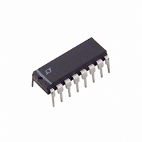
LT1158CN Linear Technology, LT1158CN Datasheet - Page 16

LT1158CN
Manufacturer Part Number
LT1158CN
Description
IC MOSFET DRVR 1/2BRDG NCH 16DIP
Manufacturer
Linear Technology
Datasheet
1.LT1158CNPBF.pdf
(22 pages)
Specifications of LT1158CN
Configuration
Half Bridge
Input Type
PWM
Current - Peak
500mA
Number Of Configurations
1
Number Of Outputs
2
High Side Voltage - Max (bootstrap)
56V
Voltage - Supply
5 V ~ 30 V
Operating Temperature
0°C ~ 70°C
Mounting Type
Through Hole
Package / Case
16-DIP (0.300", 7.62mm)
Lead Free Status / RoHS Status
Contains lead / RoHS non-compliant
Delay Time
-
Available stocks
Company
Part Number
Manufacturer
Quantity
Price
Part Number:
LT1158CN
Manufacturer:
LT/凌特
Quantity:
20 000
Part Number:
LT1158CN#PBF
Manufacturer:
LINEAR/凌特
Quantity:
20 000
LT1158
APPLICATIONS INFORMATION
from a true short. This is done by using the current limit to
control cold fi lament current in conjunction with the self-
protection circuit of Figure 9. The reduced cold fi lament
current also extends the life of the fi lament.
A good guideline is to choose R
proximately twice the steady state “on” current of the
lamp(s). t
antee that the lamp fi laments heat and drop out of current
limit before the enable capacitor discharges to the enable
low threshold. For a short-circuit, the enable capacitor
will continue to discharge below the threshold, shutting
TYPICAL APPLICATIONS
16
Q1, Q2: IRLZ44 (LOGIC-LEVEL)
L1: HURRICANE LAB
R
CONSTANT OFF TIME CURRENT MODE CONTROL LOOP
FREQUENCY =
S
CMOS
ON/OFF
: VISHAY/DALE TYPE LVR-3
HL-KK122T/BB
VISHAY/ULTRONIX RCS01, SM1
ISOTEK CORP. ISA-PLAN SMR
100k
IRFZ44 (STANDARD)
SHUTDOWN
100k
t
OFF
1
2N2222
VP0300
INSERT FOR
ZERO POWER
SHUTDOWN
(
1 –
V
Figure 10. High Effi ciency 3.3V Step-Down Switching Regulator (Requires No Heatsinks)
V
is then made long enough to guar-
OUT
IN
)
WHERE t
+
OFF
24k
≈ 10μs
SENSE
10μF
0.01μF
1000pF
to set I
1
2
3
4
5
6
7
8
BOOST DR
V
BIAS
ENABLE
FAULT
INPUT
GND
B GATE FB
+
SC
LT1158
at ap-
1N4148
B GATE DR
T GATE DR
T SOURCE
T GATE FB
SENSE
SENSE
BOOST
V
down the top MOSFET. The LT1158 will then go into the
automatic restart mode described in Self-Protection with
Automatic Restart above.
The time constant for an incandescent fi lament is tens
of milliseconds, which means that t
to be longer than in most other applications. This places
increased SOA demands on the MOSFET during a short
circuit, requiring that a larger than normal device be used.
A protected high current lamp driver application is shown
in Figure 18.
+
–
+
16
15
14
13
12
11
10
9
0.1μF
510Ω
100Ω
100Ω
0.05μF
680k
1N4148
1k
Q1
Q2
1
2
3
4
5V TO 10V INPUT (USE LOGIC-LEVEL Q1, Q2)
8V TO 20V INPUT (USE STANDARD Q1, Q2
AND CONNECT BOOST DIODE TO PIN 1)
+
22μH
L1
LT1431
500μF
LOW ESR
+
0.015Ω
R
S
8
7
6
5
SHORT-CIRCUIT
CURRENT = 8A
SHUTDOWN
–
+
4.99k
1%
1.62k
1%
1000μF
LOW ESR
+3.3V/6A
OUTPUT
LT1158 F10
will have
200pF
1158fb


