IRS2332DJPBF International Rectifier, IRS2332DJPBF Datasheet - Page 4
IRS2332DJPBF
Manufacturer Part Number
IRS2332DJPBF
Description
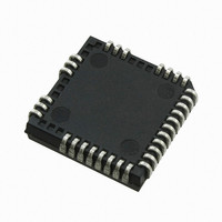
IC DVR 3-PHASE BRIDGE PLCC44
Manufacturer
International Rectifier
Datasheet
1.IRS2330JTRPBF.pdf
(36 pages)
Specifications of IRS2332DJPBF
Configuration
3 Phase Bridge
Input Type
Inverting
Delay Time
500ns
Current - Peak
250mA
Number Of Configurations
1
Number Of Outputs
3
High Side Voltage - Max (bootstrap)
600V
Voltage - Supply
10 V ~ 20 V
Operating Temperature
-40°C ~ 125°C
Mounting Type
Surface Mount
Package / Case
*
Lead Free Status / RoHS Status
Lead free / RoHS Compliant
Available stocks
Company
Part Number
Manufacturer
Quantity
Price
Company:

Part Number:
IRS2332DJPBF
Manufacturer:
International Rectifier
Quantity:
10 000


Recommended Operating Conditions
The Input/Output logic timing diagram is shown in figure 1. For proper operation the device should be used within the
recommended conditions. All voltage parameters are absolute voltage referenced to V
tested with all supplies biased at 15 V differential.
Symbol
Note 1: Logic operational for V
Note 2: Operational for transient negative VS of VSS - 50 V with a 50 ns pulse width. Guaranteed by design. Refer to
the Application Information section of this datasheet for more details.
Note 3: CAO input pin is internally clamped with a 5.2 V zener diode.
Dynamic Electrical Characteristics
NOTE: For high side PWM, HIN pulse width must be > 1.5 usec
V
www.irf.com
V
V
Symbol
V
V
V
BIAS
V
HO1,2,3
V
V
LO1,2,3
V
V
St1,2,3
V
B1,2,3
S1,2,3
T
CAO
MDT
FLT
CA-
CC
t
SS
IN
t
MT
PM
t
DT
A
t
t
flt, in
fltclr
itrip
t
t
t
t
on
off
flt
bl
(V
r
f
CC
, V
BS1,2,3
High Side Floating Supply Voltage
Static High side floating offset voltage
Transient High side floating offset voltage
High Side Floating Output Voltage
Low Side and Logic Fixed Supply Voltage
Logic Ground
Low Side Output Voltage
Operational Amplifier Inverting Input Voltage
Ambient temperature
Logic Input Voltage (HIN1,2,3, LIN1,2,3 & ITRIP)
FAULT Output Voltage
Operational Amplifier Output Voltage
Turn-on propagation delay
Turn-off propagation delay
Turn-on rise time
Turn-off fall time
ITRIP to Output Shutdown Propagation Delay
ITRIP Blanking Time
ITRIP to FAULT Indication Delay
Input Filter Time (All Six Inputs)
LIN1,2,3 to FAULT Clear Time (2330/2)
Deadtime:
Deadtime matching: :
Delay matching time (t
Pulse width distortion
) = 15 V, V
SO1,2,3
S
of (V
Definition
= V
SO
Definition
SS
-8 V) to (V
ON
, C
, t
L
OFF
= 1000 pF, T
)
SO
(IRS2332(D))
(IRS2330(D))
(IRS2330(D))
(IRS2332(D))
+600 V). Logic state held for V
A
= 25 °C unless otherwise specified.
5300 8500 13700
1300 2000 3100
Min Typ Max Units Test Conditions
400
400
400
350
500
—
—
—
—
—
—
—
—
550
500
500
660
400
325
700
80
35
—
—
—
—
V
IRS233(0,2)(D)(S&J)PbF
1100
700
700
870
-50 (Note2)
S
125
920
400
140
SO
V
55
50
75
—
—
of (V
S1,2,3
SO.
-8 (Note1)
V
Min.
V
V
V
V
-40
S1,2,3
10
-5
0
SS
SS
SS
SS
The V
+10
SO
ns
-8 V) to (V
S
offset rating is
V
V
V
V
V
S1,2,3
Max.
external deadtime
external deadtime
V
S1,2,3
SS
SS
SS
600
600
V
V
125
PM input 10 µs
B1,2,3
20
larger than DT
5
V
V
CC
CC
SO
V
+ 5
+ 5
+ 5
IN
IN
+20
S1,2,3
= 0 V to 600 V
= 0 V & 5 V
= 0 V & 5 V
– V
without
without
BS
= 0 V
)
Units
.
°C
V
4
Related parts for IRS2332DJPBF
Image
Part Number
Description
Manufacturer
Datasheet
Request
R

Part Number:
Description:
SCHOTTKY RECTIFIER
Manufacturer:
International Rectifier Corp.
Datasheet:
Part Number:
Description:
SCHOTTKY RECTIFIER
Manufacturer:
International Rectifier Corp.
Datasheet:
Part Number:
Description:
SCHOTTKY RECTIFIER
Manufacturer:
International Rectifier Corp.
Datasheet:
Part Number:
Description:
SCHOTTKY RECTIFIER
Manufacturer:
International Rectifier Corp.
Datasheet:
Part Number:
Description:
SCHOTTKY RECTIFIER
Manufacturer:
International Rectifier Corp.
Datasheet:
Part Number:
Description:
SCHOTTKY RECTIFIER
Manufacturer:
International Rectifier Corp.
Datasheet:
Part Number:
Description:
SCHOTTKY RECTIFIER
Manufacturer:
International Rectifier Corp.
Datasheet:
Part Number:
Description:
SCHOTTKY RECTIFIER
Manufacturer:
International Rectifier Corp.
Datasheet:
Part Number:
Description:
SCHOTTKY RECTIFIER
Manufacturer:
International Rectifier Corp.
Datasheet:
Part Number:
Description:
SCHOTTKY RECTIFIER
Manufacturer:
International Rectifier Corp.
Datasheet:
Part Number:
Description:
SCHOTTKY RECTIFIER
Manufacturer:
International Rectifier Corp.
Datasheet:
Part Number:
Description:
SCHOTTKY RECTIFIER
Manufacturer:
International Rectifier Corp.
Datasheet:
Part Number:
Description:
SCHOTTKY RECTIFIER
Manufacturer:
International Rectifier Corp.
Datasheet:
Part Number:
Description:
SCHOTTKY RECTIFIER
Manufacturer:
International Rectifier Corp.
Datasheet:
Part Number:
Description:
SCHOTTKY RECTIFIER
Manufacturer:
International Rectifier Corp.
Datasheet: