ADP3110AKCPZ-RL ON Semiconductor, ADP3110AKCPZ-RL Datasheet
ADP3110AKCPZ-RL
Specifications of ADP3110AKCPZ-RL
Available stocks


Related parts for ADP3110AKCPZ-RL

ADP3110AKCPZ-RL Summary of contents
Page 1
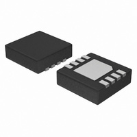
... View) ORDERING INFORMATION Device Package ADP3110AKRZ SO−8 (Pb−Free) ADP3110AKRZ−RL SO−8 (Pb−Free) ADP3110AKCPZ−RL DFN8 (Pb−Free) †For information on tape and reel specifications, including part orientation and tape sizes, please refer to our Tape and Reel Packaging Specification Brochure, BRD8011/D. 1 MARKING DIAGRAMS ...
Page 2
OD V TSD CC UVLO 2 IN START STOP MIN DRVL OFF TIMER PIN DESCRIPTION SO−8 DFN8 Symbol 1 1 BST Upper MOSFET Floating Bootstrap Supply. A capacitor connected between BST and SW pins holds this bootstrap voltage for ...
Page 3
MAXIMUM RATINGS Operating Ambient Temperature Operating Junction Temperature, T (Note 1) J Package Thermal Resistance: SO−8 Junction−to−Case, R qJC Junction−to−Ambient, R (2−Layer Board) qJA Package Thermal Resistance: DFN8 (Note 2) Junction−to−Case, R (From die to exposed pad) qJC ...
Page 4
ELECTRICAL CHARACTERISTICS Characteristic Supply Supply Voltage Range Supply Current OD Input Input Voltage High Input Voltage Low Hysteresis Input Current PWM Input Input Voltage High Input Voltage Low Hysteresis Input Current High−Side Driver Output Resistance, Sourcing Current Output Resistance, Sinking ...
Page 5
Theory of Operation The ADP3110A are single phase MOSFET drivers designed for driving two N−channel MOSFETs in a synchronous buck converter topology. The ADP3110A will operate from 5 but have been optimized for high current multi−phase ...
Page 6
OD V OD_LO DRVH or DRVL Figure 2. Output Disable Timing Diagram V PWM_HI pdlDRVL fDRVL 90% DRVL 2V DRVH−SW SW Figure 3. Nonoverlap Timing Diagram Output Enable 2 PWM in Figure 4. ...
Page 7
... 0.10 0.05 BOTTOM VIEW *For additional information on our Pb−Free strategy and soldering details, please download the ON Semiconductor Soldering and Mounting Techniques Reference Manual, SOLDERRM/D. PACKAGE DIMENSIONS DFN8 3x3, 0.5P CASE 506BJ−01 ISSUE O EDGE OF PACKAGE L L1 DETAIL A OPTIONAL CONSTRUCTION L DETAIL A OPTIONAL ...
Page 8
... *For additional information on our Pb−Free strategy and soldering details, please download the ON Semiconductor Soldering and Mounting Techniques Reference Manual, SOLDERRM/D. FlexMode is a trademark of Analog Devices, Inc. ON Semiconductor and are registered trademarks of Semiconductor Components Industries, LLC (SCILLC). SCILLC reserves the right to make changes without further notice to any products herein ...