MC33153PG ON Semiconductor, MC33153PG Datasheet - Page 8
MC33153PG
Manufacturer Part Number
MC33153PG
Description
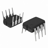
IC DRIVER GATE SINGLE IGBT 8DIP
Manufacturer
ON Semiconductor
Type
Single IGBT Gate Driverr
Datasheet
1.MC33153PG.pdf
(13 pages)
Specifications of MC33153PG
Configuration
Low-Side
Input Type
Non-Inverting
Delay Time
80ns
Current - Peak
1A
Number Of Configurations
1
Number Of Outputs
1
Voltage - Supply
11 V ~ 20 V
Operating Temperature
-40°C ~ 105°C
Mounting Type
Through Hole
Package / Case
8-DIP (0.300", 7.62mm)
Supply Current
20 mA
Mounting Style
Through Hole
Lead Free Status / RoHS Status
Lead free / RoHS Compliant
High Side Voltage - Max (bootstrap)
-
Lead Free Status / Rohs Status
Lead free / RoHS Compliant
Other names
MC33153PGOS
Available stocks
Company
Part Number
Manufacturer
Quantity
Price
Company:

Part Number:
MC33153PG
Manufacturer:
IXSY
Quantity:
772
Company:
Part Number:
MC33153PG
Manufacturer:
ON Semiconductor
Quantity:
422
Part Number:
MC33153PG
Manufacturer:
ON/安森美
Quantity:
20 000


GATE DRIVE
Controlling Switching Times
is optimization of the switching characteristics. The
switching characteristics are especially important in motor
control applications in which PWM transistors are used in a
bridge configuration. In these applications, the gate drive
circuit components should be selected to optimize turn−on,
turn−off and off−state impedance. A single resistor may be
used to control both turn−on and turn−off as shown in
Figure 31. However, the resistor value selected must be a
compromise in turn−on abruptness and turn−off losses.
Using a single resistor is normally suitable only for very low
frequency PWM. An optimized gate drive output stage is
shown in Figure 32. This circuit allows turn−on and turn−off
to be optimized separately. The turn−on resistor, R
provides control over the IGBT turn−on speed. In motor
control circuits, the resistor sets the turn−on di/dt that
controls how fast the free−wheel diode is cleared. The
interaction of the IGBT and free−wheeling diode determines
The most important design aspect of an IGBT gate drive
8.0
6.0
4.0
2.0
10
0
5.0
Figure 28. Supply Current versus
V
CC
10
Supply Voltage
, SUPPLY VOLTAGE (V)
80
60
40
20
0
Figure 30. Supply Current versus Input Frequency
1.0
15
V
T
A
CC
= 25°C
Output High
Output Low
= 15 V
OPERATING DESCRIPTION
T
A
= 25°C
f, INPUT FREQUENCY (kHz)
http://onsemi.com
10
on
20
,
8
the turn−on dv/dt. Excessive turn−on dv/dt is a common
problem in half−bridge circuits. The turn−off resistor, R
controls the turn−off speed and ensures that the IGBT
remains off under commutation stresses. Turn−off is critical
to obtain low switching losses. While IGBTs exhibit a fixed
minimum loss due to minority carrier recombination, a slow
gate drive will dominate the turn−off losses. This is
particularly true for fast IGBTs. It is also possible to turn−off
an IGBT too fast. Excessive turn−off speed will result in
large overshoot voltages. Normally, the turn−off resistor is
a small fraction of the turn−on resistor.
that is capable of sourcing 1.0 amp and sinking 2.0 amps
peak. This output also contains a pull down resistor to ensure
that the IGBT is off whenever there is insufficient V
MC33153.
configuration. Thus, at least one device is always off. While
The MC33153 contains a bipolar totem pole output stage
In a PWM inverter, IGBTs are used in a half−bridge
8.0
6.0
4.0
2.0
10
-60
0
100
Figure 29. Supply Current versus Temperature
-40
C
-20
L
= 5.0 nF
= 2.0 nF
= 1.0 nF
= 10 nF
T
A
, AMBIENT TEMPERATURE (°C)
0
1000
20
40
60
V
V
Drive Output Open
80
CC
Pin 4
= 15 V
= V
100
CC
CC
120
to the
140
off
,
Related parts for MC33153PG
Image
Part Number
Description
Manufacturer
Datasheet
Request
R

Part Number:
Description:
ON Semiconductor [VOLTAGE REGULATOR]
Manufacturer:
ON Semiconductor
Datasheet:
Part Number:
Description:
357-036-542-201 CARDEDGE 36POS DL .156 BLK LOPRO
Manufacturer:
ON Semiconductor
Datasheet:
Part Number:
Description:
357-036-542-201 CARDEDGE 36POS DL .156 BLK LOPRO
Manufacturer:
ON Semiconductor
Datasheet:
Part Number:
Description:
357-036-542-201 CARDEDGE 36POS DL .156 BLK LOPRO
Manufacturer:
ON Semiconductor
Datasheet:
Part Number:
Description:
357-036-542-201 CARDEDGE 36POS DL .156 BLK LOPRO
Manufacturer:
ON Semiconductor
Datasheet:
Part Number:
Description:
357-036-542-201 CARDEDGE 36POS DL .156 BLK LOPRO
Manufacturer:
ON Semiconductor
Datasheet:
Part Number:
Description:
357-036-542-201 CARDEDGE 36POS DL .156 BLK LOPRO
Manufacturer:
ON Semiconductor
Datasheet:
Part Number:
Description:
357-036-542-201 CARDEDGE 36POS DL .156 BLK LOPRO
Manufacturer:
ON Semiconductor
Datasheet:
Part Number:
Description:
357-036-542-201 CARDEDGE 36POS DL .156 BLK LOPRO
Manufacturer:
ON Semiconductor
Datasheet:
Part Number:
Description:
357-036-542-201 CARDEDGE 36POS DL .156 BLK LOPRO
Manufacturer:
ON Semiconductor
Datasheet:
Part Number:
Description:
357-036-542-201 CARDEDGE 36POS DL .156 BLK LOPRO
Manufacturer:
ON Semiconductor
Datasheet:
Part Number:
Description:
Manufacturer:
ON Semiconductor
Datasheet:
Part Number:
Description:
Manufacturer:
ON Semiconductor
Datasheet:
Part Number:
Description:
Manufacturer:
ON Semiconductor
Datasheet: