IR2109 International Rectifier, IR2109 Datasheet - Page 3
IR2109
Manufacturer Part Number
IR2109
Description
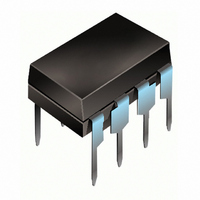
IC DRIVER HALF-BRIDGE 8-DIP
Manufacturer
International Rectifier
Datasheet
1.IR2109STRPBF.pdf
(25 pages)
Specifications of IR2109
Configuration
Half Bridge
Input Type
Non-Inverting
Delay Time
750ns
Current - Peak
200mA
Number Of Configurations
1
Number Of Outputs
2
High Side Voltage - Max (bootstrap)
600V
Voltage - Supply
10 V ~ 20 V
Operating Temperature
-40°C ~ 125°C
Mounting Type
Through Hole
Package / Case
8-DIP (0.300", 7.62mm)
Lead Free Status / RoHS Status
Contains lead / RoHS non-compliant
Other names
*IR2109
Available stocks
Company
Part Number
Manufacturer
Quantity
Price

Part Number:
IR2109
Manufacturer:
IR
Quantity:
20 000
Part Number:
IR2109(BLACK)
Manufacturer:
IR
Quantity:
20 000
Company:
Part Number:
IR21091
Manufacturer:
Panasonic
Quantity:
3 065
Part Number:
IR21091SPBF
Manufacturer:
INFINEON/英飞凌
Quantity:
20 000
Part Number:
IR21091STRPBF
Manufacturer:
IR
Quantity:
20 000
Part Number:
IR21094
Manufacturer:
IR
Quantity:
20 000


Note 1: Logic operational for V
DT97-3 for more details).
www.irf.com
Recommended Operating Conditions
The input/output logic timing diagram is shown in figure 1. For proper operation the device should be used within the
recommended conditions. The V
Dynamic Electrical Characteristics
V
Symbol
Symbol
BIAS
MDT
V
V
V
V
t on
t off
MT
V
t sd
DT
VB
V
DT
T
t r
t f
HO
CC
LO
SS
IN
A
(V
S
CC
, V
BS
Turn-on propagation delay
Turn-off propagation delay
Shut-down propagation delay
Delay matching, HS & LS turn-on/off
Turn-on rise time
Turn-off fall time
Deadtime: LO turn-off to HO turn-on(DT
Deadtime matching = DT
High side floating supply absolute voltage
High side floating supply offset voltage
High side floating output voltage
Low side and logic fixed supply voltage
Low side output voltage
Logic input voltage (IN & SD)
Programmable dead-time pin voltage (IR21094 only)
Logic ground (IR21094 only)
Ambient temperature
) = 15V, V
HO turn-off to LO turn-on (DT
SS
Definition
= COM, C
S
S
of -5 to +600V. Logic state held for V
and V
LO - HO
Definition
L
SS
= 1000 pF, T
offset rating are tested with all supplies biased at 15V differential.
- DT
HO-LO
LO-HO) &
A
HO-LO)
= 25°C, DT = VSS unless otherwise specified.
Min.
—
—
—
—
—
—
400
4
—
—
S
IR2109 ( 4 ) (
of -5V to -V
Typ.
750
200
200
150
540
50
0
5
0
0
BS
V
Max. Units Test Conditions
Note 1
Min.
S
950
280
220
V
V
280
680
600
. (Please refer to the Design Tip
-40
70
V
80
60
10
-5
6
0
SS
SS
+ 10
S
nsec
usec
nsec
S
V
Max.
) & (PbF)
S
V
V
V
RDT = 200k
600
125
RDT = 200k
V
20
CC
CC
CC
5
+ 20
V
B
S
= 0V or 600V
V
V
V
RDT= 0
RDT=0
S
S
S
= 0V
= 0V
= 0V
Units
(IR21094)
°
(IR21094)
C
V
3
Related parts for IR2109
Image
Part Number
Description
Manufacturer
Datasheet
Request
R

Part Number:
Description:
SCHOTTKY RECTIFIER
Manufacturer:
International Rectifier Corp.
Datasheet:
Part Number:
Description:
SCHOTTKY RECTIFIER
Manufacturer:
International Rectifier Corp.
Datasheet:
Part Number:
Description:
SCHOTTKY RECTIFIER
Manufacturer:
International Rectifier Corp.
Datasheet:
Part Number:
Description:
SCHOTTKY RECTIFIER
Manufacturer:
International Rectifier Corp.
Datasheet:
Part Number:
Description:
SCHOTTKY RECTIFIER
Manufacturer:
International Rectifier Corp.
Datasheet:
Part Number:
Description:
SCHOTTKY RECTIFIER
Manufacturer:
International Rectifier Corp.
Datasheet:
Part Number:
Description:
SCHOTTKY RECTIFIER
Manufacturer:
International Rectifier Corp.
Datasheet:
Part Number:
Description:
SCHOTTKY RECTIFIER
Manufacturer:
International Rectifier Corp.
Datasheet:
Part Number:
Description:
SCHOTTKY RECTIFIER
Manufacturer:
International Rectifier Corp.
Datasheet:
Part Number:
Description:
SCHOTTKY RECTIFIER
Manufacturer:
International Rectifier Corp.
Datasheet:
Part Number:
Description:
SCHOTTKY RECTIFIER
Manufacturer:
International Rectifier Corp.
Datasheet:
Part Number:
Description:
SCHOTTKY RECTIFIER
Manufacturer:
International Rectifier Corp.
Datasheet:
Part Number:
Description:
SCHOTTKY RECTIFIER
Manufacturer:
International Rectifier Corp.
Datasheet:
Part Number:
Description:
SCHOTTKY RECTIFIER
Manufacturer:
International Rectifier Corp.
Datasheet:
Part Number:
Description:
SCHOTTKY RECTIFIER
Manufacturer:
International Rectifier Corp.
Datasheet: