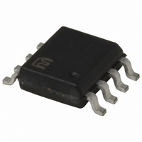
MIC5011BM Micrel Inc, MIC5011BM Datasheet - Page 8

MIC5011BM
Manufacturer Part Number
MIC5011BM
Description
IC DRIVER MIN PARTS HI/LO 8SOIC
Manufacturer
Micrel Inc
Datasheet
1.MIC5011YM.pdf
(12 pages)
Specifications of MIC5011BM
Configuration
High or Low Side
Input Type
Non-Inverting
Delay Time
25µs
Number Of Configurations
1
Number Of Outputs
1
Voltage - Supply
4.75 V ~ 32 V
Operating Temperature
-40°C ~ 85°C
Mounting Type
Surface Mount
Package / Case
8-SOIC (3.9mm Width)
Lead Free Status / RoHS Status
Lead free / RoHS Compliant
Current - Peak
-
High Side Voltage - Max (bootstrap)
-
Available stocks
Company
Part Number
Manufacturer
Quantity
Price
Part Number:
MIC5011BM
Manufacturer:
MICREL/麦瑞
Quantity:
20 000
MIC5011
Applications Information
Opto-Isolated Interface (Figure 5). Although the MIC5011
has no special input slew rate requirement, the lethargic
transitions provided by an opto-isolator may cause oscil-
lations on the rise and fall of the output. The circuit shown
accelerates the input transitions from a 4N35 opto-isolator
by adding hysteresis. Opto-isolators are used where the
control circuitry cannot share a common ground with the
MIC5011 and high-current power supply, or where the
control circuitry is located remotely. This implementation is
intrinsically safe; if the control line is severed the MIC5011
will turn OFF.
Industrial Switch (Figure 6). The most common manual
control for industrial loads is a push button on/off switch.
The “on” button is physically arranged in a recess so that
in a panic situation the “off” button, which extends out
from the control box, is more easily pressed. This circuit is
MIC5011
Control Input
Figure 4. Bootstrapped
1
2
3
4
CR2943-NA102A
( GE )
V+
Source
Gnd
Input
High-Side Driver
MIC5011
100nF
Gate
Com
C2
C1
1N5817
8
7
6
5
O F F
ON
(Continued)
+
10µF
100kΩ
7 to 15V
LOAD
330kΩ
1N4001 (2)
IRF540
Figure 6. 50-Ampere
1
2
3
4
Industrial Switch
V+
Source
Gnd
Input
MIC5011
8
Gate
Com
C2
compatible with control boxes such as the CR2943 series
(GE). The circuit is configured so that if both switches close
simultaneously, the “off” button has precedence.
This application also illustrates how two (or more) MOS-
FETs can be paralleled. This reduces the switch drop, and
distributes the switch dissipation into multiple packages.
High-Voltage Bootstrap (Figure 7). Although the MIC5011
is limited to operation on 4.75 to 32V supplies, a floating
bootstrap arrangement can be used to build a high-side
switch that operates on much higher voltages. The MIC5011
and MOSFET are configured as a low-side driver, but the
load is connected in series with ground.
Power for the MIC5011 is supplied by a charge pump. A
20kHz square wave (15Vp-p) drives the pump capacitor
and delivers current to a 100µF storage capacitor. A zener
C1
8
7
6
5
Control Input
10mA
+
10µF
Opto-Isolator Performance
LOAD
24V
Figure 5. Improved
100kΩ
4N35
IRFP044 (2)
33pF
15V
100kΩ
1kΩ
33kΩ
MPSA05
To MIC5011
July 2005
Micrel, Inc.
Input


