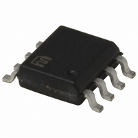
MIC5013BM Micrel Inc, MIC5013BM Datasheet - Page 2

MIC5013BM
Manufacturer Part Number
MIC5013BM
Description
IC DRIVER MOSF HI/LO SIDE 8SOIC
Manufacturer
Micrel Inc
Datasheet
1.MIC5013YM.pdf
(15 pages)
Specifications of MIC5013BM
Configuration
High or Low Side
Input Type
Non-Inverting
Delay Time
60µs
Number Of Configurations
1
Number Of Outputs
1
Voltage - Supply
7 V ~ 32 V
Operating Temperature
-40°C ~ 85°C
Mounting Type
Surface Mount
Package / Case
8-SOIC (3.9mm Width)
Number Of Drivers
1
Driver Type
High Side/Low Side
Operating Supply Voltage (max)
32V
Power Dissipation
1.25W
Operating Supply Voltage (min)
7V
Operating Supply Voltage (typ)
15V
Turn Off Delay Time
4us
Turn On Delay Time (max)
60us
Operating Temp Range
-40C to 85C
Operating Temperature Classification
Industrial
Mounting
Surface Mount
Pin Count
8
Package Type
SOIC
Lead Free Status / RoHS Status
Contains lead / RoHS non-compliant
Current - Peak
-
High Side Voltage - Max (bootstrap)
-
Lead Free Status / Rohs Status
Not Compliant
Available stocks
Company
Part Number
Manufacturer
Quantity
Price
Part Number:
MIC5013BM
Manufacturer:
MICREL
Quantity:
20 000
Company:
Part Number:
MIC5013BM/YM
Manufacturer:
MICREL
Quantity:
300
MIC5013
Absolute Maximum Ratings
Input Voltage, Pin 1
Threshold Voltage, Pin 2
Sense Voltage, Pin 3
Source Voltage, Pin 4
Current into Pin 4
Gate Voltage, Pin 6
Supply Voltage (V
Fault Output Current, Pin 8
Junction Temperature
Pin Description
Pin Configuration
MIC5013
Pin Number
1
2
3
4
5
6
7
8
+
), Pin 7
(Refer to Figures 1 and 2)
Pin Name
Threshold
Ground
Source
Sense
Input
Gate
Fault
V
+
(Note 1, 2)
–1mA to +1mA
–0.5V to 36V
–0.5 to +5V
–1V to 50V
–10V to V
–10V to V
–10 to V
Pin Function
Resets current sense latch and turns on power MOSFET when taken above
threshold (3.5V typical). Pin 1 requires <1µA to switch.
Sets current sense trip voltage according to:
where R
trip voltage at turn-on to 2V. Use C
stant.
The sense pin causes the current sense to trip when V
V
a 3 lead FET or a resistor R
Reference for the current sense voltage on pin 3 and return for the gate
clamp zener. Connect to the load side of current shunt or kelvin lead of cur-
rent sensing FET. Pins 3 and 4 can safely swing to –10V when turning off
inductive loads.
Drives and clamps the gate of the power FET. Pin 6 will be clamped to ap-
proximately –0.7V by an internal diode when turning off inductive loads.
Supply pin; must be decoupled to isolate from large transients caused by
the power FET drain. 10µF is recommended close to pins 7 and 5.
Outputs status of protection circuit when pin 1 is high. Fault low indicates
normal operation; fault high indicates current sense tripped.
150°C
50mA
1
2
3
4
SOURCE
Input
Thresh
Sense
Source
MIC5013
+
+
+
TH
. Pin 3 is used in conjunction with a current shunt in the source of
2
to ground is 3.3k to 20kΩ. Adding capacitor C
Fault
Gate
Gnd
Operating Ratings
Power Dissipation
θ
θ
Ambient Temperature: B version
Storage Temperature
Lead Temperature
(Soldering, 10 seconds)
Supply Voltage (V
V+
JA
JA
(Plastic DIP)
(SOIC)
8
7
6
5
S
in the sense lead of a current sensing FET.
+
), Pin 7
V
TH
TR I P
=10µF for a 10ms turn-on time con-
=
(Notes 1, 2)
R
TH
2200
+ 1000
7V to 32V high side
SENSE
7V to 15V low side
–65°C to +150°C
TH
–40°C to +85°C
increases the
is V
TRIP
July 2005
100°C/W
170°C/W
Micrel, Inc.
1.25W
260°C
above


