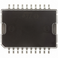
L298P013TR STMicroelectronics, L298P013TR Datasheet - Page 4

L298P013TR
Manufacturer Part Number
L298P013TR
Description
IC DRIVER FULL DUAL 20-PWRSOIC
Manufacturer
STMicroelectronics
Type
H Bridger
Datasheet
1.L298P.pdf
(13 pages)
Specifications of L298P013TR
Input Type
Non-Inverting
Number Of Outputs
4
Current - Output / Channel
2A
Current - Peak Output
3A
Voltage - Supply
4.5 V ~ 46 V
Operating Temperature
-25°C ~ 130°C
Mounting Type
Surface Mount
Package / Case
PowerSO-20 Exposed Bottom Pad
Input Voltage Range
+ 2.5 V to + 46 V
Operating Temperature Range
- 25 C to + 130 C
Mounting Style
SMD/SMT
Lead Free Status / RoHS Status
Lead free / RoHS Compliant
On-state Resistance
-
Lead Free Status / Rohs Status
Lead free / RoHS Compliant
Other names
497-3624-2
Available stocks
Company
Part Number
Manufacturer
Quantity
Price
Part Number:
L298P013TR
Manufacturer:
ST
Quantity:
20 000
Company:
Part Number:
L298P013TR L297 L293 L6506 L6202 L6203 L
Manufacturer:
ST
0
1) 1)Sensing voltage can be –1 V for t 50 sec; in steady state V
2) See fig. 2.
3) See fig. 4.
4) The load must be a pure resistor.
L298
ELECTRICAL CHARACTERISTICS (continued)
Figure 1 : Typical Saturation Voltage vs. Output
4/13
Symbol
T
T
T
T
T
T
T
T
T
T
T
T
T
T
T
T
fc (V
1
2
3
4
5
6
7
8
1
2
3
4
5
6
7
8
(V
(V
(V
(V
(V
(V
(V
(V
(V
(V
(V
(V
(V
(V
(V
(V
en
en
en
en
en
en
en
en
i
i
i
i
i
i
i
i
i
)
)
)
)
)
)
)
)
)
)
)
)
)
)
)
)
)
Source Current Turn-off Delay
Source Current Fall Time
Source Current Turn-on Delay
Source Current Rise Time
Sink Current Turn-off Delay
Sink Current Fall Time
Sink Current Turn-on Delay
Sink Current Rise Time
Commutation Frequency
Source Current Turn-off Delay
Source Current Fall Time
Source Current Turn-on Delay
Source Current Rise Time
Sink Current Turn-off Delay
Sink Current Fall Time
Sink Current Turn-on Delay
Sink Current Rise Time
Current.
Parameter
0.5 V
0.9 I
0.5 V
0.1 I
0.5 V
0.9 I
0.5 V
0.1 I
I
0.5 V
0.9 I
0.5 V
0.1 I
0.5 V
0.9 I
0.5 V
0.1 I
L
= 2A
L
L
L
L
L
L
L
L
i
i
i
i
en
en
en
en
to 0.9 I
to 0.1 I
to 0.9 I
to 0.9 I
to 0.1 I
to 0.9 I
to 0.1 I
to 0.9 I
to 0.1 I
to 0.9 I
to 0.1 I
to 0.9 I
to 0.9 I
to 0.1 I
to 0.9 I
to 0.9 I
sens
Test Conditions
min
L
L
L
L
L
L
L
L
L
L
L
L
L
L
L
L
Figure 2 : Switching Times Test Circuits.
Note : For INPUT Switching, set EN = H
– 0.5 V.
(2); (4)
(2); (4)
(3); (4)
(3); (4)
(2); (4)
(2); (4)
(3); (4)
(3); (4)
(2); (4)
(2); (4)
(3); (4)
(3); (4)
(2); (4)
(2); (4)
(3); (4)
(3); (4)
For ENABLE Switching, set IN = H
Min.
Typ.
0.25
0.35
0.25
1.5
0.2
0.7
0.7
1.6
0.2
0.3
0.4
2.2
0.1
25
2
3
1
Max.
40
Unit
KHz
s
s
s
s
s
s
s
s
s
s
s
s
s
s
s
s


