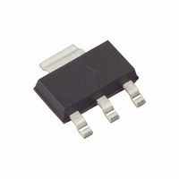
BSP75NTA Diodes Zetex, BSP75NTA Datasheet - Page 4

BSP75NTA
Manufacturer Part Number
BSP75NTA
Description
MOSFET N-CH 60V 1.2A SOT-223
Manufacturer
Diodes Zetex
Series
INTELLIFET™r
Type
Low Sider
Datasheet
1.BSP75NTA.pdf
(8 pages)
Specifications of BSP75NTA
Input Type
Non-Inverting
Number Of Outputs
1
On-state Resistance
385 mOhm
Current - Output / Channel
1.3A
Current - Peak Output
1.8A
Voltage - Supply
2.2 V ~ 10 V
Operating Temperature
-40°C ~ 150°C
Mounting Type
Surface Mount
Package / Case
SOT-223 (3 leads + Tab), SC-73, TO-261
Switch Type
Low Side
Power Switch Family
BSP75N
Input Voltage
-0.2 to 20V
Power Switch On Resistance
520mOhm
Output Current
700mA
Mounting
Surface Mount
Package Type
SOT-223
Operating Temperature (min)
-40C
Operating Temperature (max)
150C
Operating Temperature Classification
Automotive
Pin Count
3 +Tab
Power Dissipation
1.5W
Lead Free Status / RoHS Status
Lead free / RoHS Compliant
Lead Free Status / RoHS Status
Lead free / RoHS Compliant, Compliant
Other names
BSP75NTR
Available stocks
Company
Part Number
Manufacturer
Quantity
Price
Part Number:
BSP75NTA
Manufacturer:
DIODES/美台
Quantity:
20 000
Electrical characteristics (at T
Issue 4 - September 2006
© Zetex Semiconductors plc 2006
(*) The drain current is limited to a reduced value when V
(†) Protection features may operate outside spec for V
(‡) Integrated protection functions are designed to prevent IC destruction under fault conditions described in the
NOTES:
Parameter
Static characteristics
Drain-source clamp voltage
Off-state drain current
Off-state drain current
Input threshold voltage
Input current
Input current
Input current
Static drain-source on-state
resistance
Static drain-source on-state
resistance
Current limit
Current limit
Dynamic characteristics
Turn-on time (V
Turn-off time (V
Slew rate on (70 to 50% V
Slew rate off (50 to 70% V
Protection functions
Required input voltage for
over temperature protection
Thermal overload trip
temperature
Thermal hysteresis
Unclamped single pulse
inductive energy T
Unclamped single pulse
inductive energy T
Inverse diode
Source drain voltage
datasheet. Fault conditions are considered as "outside" normal operating range. Protection functions are not designed
for continuous, repetitive operation.
(†)
(†)
IN
IN
to 90% I
to 90% I
j
j
=25°C
=150°C
(‡)
(*)
DD
DD
D
D
)
)
)
)
Symbol
V
I
I
V
I
I
I
R
R
I
I
t
t
-dV
DV
V
T
E
V
DSS
DSS
IN
IN
IN
D(LIM)
D(LIM)
on
off
JT
AS
DS(AZ)
IN(th)
DS(on)
DS(on)
PROT
SD
DS
AMB
DS
/dt
/dt
off
on
= 25°C unless otherwise stated)
IN
<4.5V.
Min.
150
550
200
0.7
1.0
4.5
DS
60
1
4
exceeds a safe level.
Typ.
520
385
175
0.1
2.1
0.7
1.5
1.0
1.8
3.0
3.2
70
13
3
4
8
1
Max.
675
550
1.2
2.7
1.5
2.3
75
15
10
20
20
10
3
7
1
V/ s
V/ s
Unit
mA
mA
mA
m
m
mJ
mJ
°C
°C
A
A
V
V
V
V
A
A
s
s
Conditions
V
V
V
I
V
V
V
V
V
V
V
R
V
R
V
R
V
R
V
I
V
I
V
V
D
D(ISO)
D(ISO)
DS
DS
DS
IN
IN
IN
IN
IN
IN
IN
L
IN
L
IN
L
IN
L
IN
DD
DD
IN
=10mA
=22 , V
=22 , V
=22 , V
=22 , V
=+5V
=+7V
=+10V
=+5V, I
=+10V, I
=+5V, V
=+10V, V
=0 to +10V
=+10V to 0V
=0 to +10V
=+10V to 0V
=0V, -I
=12V, V
=32V, V
=V
=32V
=32V
www.zetex.com
=0.7A,
=0.7A,
BSP75N
GS
, I
D
D
DD
DD
DD
DD
=1.4A
D
D
=0.7A
IN
IN
DS
=1mA
=0.7A
DS
=12V,
=12V,
=12V,
=12V,
=0V
=0V
>5V
>5V


