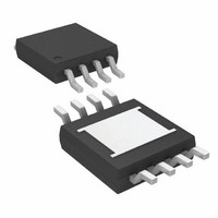
LTC4440EMS8E#TR Linear Technology, LTC4440EMS8E#TR Datasheet - Page 3

LTC4440EMS8E#TR
Manufacturer Part Number
LTC4440EMS8E#TR
Description
IC DRIVER HIGH SIDE HS/HV 8MSOP
Manufacturer
Linear Technology
Type
High Sider
Datasheet
1.LTC4440ES6TRMPBF.pdf
(12 pages)
Specifications of LTC4440EMS8E#TR
Input Type
Non-Inverting
Number Of Outputs
1
On-state Resistance
1.5 Ohm
Current - Output / Channel
2.4A
Current - Peak Output
4A
Voltage - Supply
8 V ~ 15 V
Operating Temperature
-40°C ~ 85°C
Mounting Type
Surface Mount
Package / Case
8-MSOP Exposed Pad, 8-HMSOP, 8-eMSOP
Lead Free Status / RoHS Status
Contains lead / RoHS non-compliant
Available stocks
Company
Part Number
Manufacturer
Quantity
Price
ELECTRICAL CHARACTERISTICS
SYMBOL
Output Gate Driver (TG)
V
V
I
R
Switching Timing
t
t
t
t
Note 1: Absolute Maximum Ratings are those values beyond which the life
of a device may be impaired.
Note 2: The LTC4440 is guaranteed to meet performance specifications
from 0°C to 70°C. Specifications over the –40°C to 85°C operating
temperature range are assured by design, characterization and correlation
with statistical process controls.
temperature range, otherwise specifications are at T
TYPICAL PERFOR A CE CHARACTERISTICS
PU
r
f
PLH
PHL
OH
OL
DS
300
250
200
150
100
50
0
0
V
vs Voltage
T
CC
A
= 25°C
Supply Quiescent Current
PARAMETER
High Output Voltage
Low Output Voltage
Peak Pull-Up Current
Output Pull-Down Resistance
Output Rise Time
Output Fall Time
Output Low-High Propagation Delay
Output High-Low Propagation Delay
V
CC
SUPPLY VOLTAGE (V)
5
INP = 0V
10
W
INP = V
4440 G01
CC
U
15
500
450
400
350
300
250
200
150
100
50
0
0
BOOST – TS Supply Quiescent
Current vs Voltage
A
CONDITIONS
I
I
10% – 90%, C
10% – 90%, C
10% – 90%, C
10% – 90%, C
TG
TG
T
A
= 25°C. V
= 25°C
= –10mA, V
= 100mA
BOOST – TS SUPPLY VOLTAGE (V)
The
●
5
CC
L
L
L
L
denotes specifications which apply over the full operating
OH
= V
= 1nF
= 10nF
= 1nF
= 10nF
INP = V
INP = 0V
= V
BOOST
Note 3: T
dissipation PD according to the following formula:
Note 4: Failure to solder the exposed back side of the MS8E package to
the PC board will result in a thermal resistance much higher than 40°C/W.
BOOST
T
CC
J
10
= T
= 12V, V
– V
J
A
is calculated from the ambient temperature T
+ (PD • θ
TG
4440 G02
TS
15
= GND = 0V, unless otherwise noted.
JA
°C/W)
170
165
160
155
140
150
145
●
●
●
●
●
8
Output Low Voltage (V
vs Supply Voltage
MIN
1.7
9
BOOST – TS SUPPLY VOLTAGE (V)
10
TYP
150
100
0.7
2.4
1.5
10
70
30
28
7
11
LTC4440
12
A
and power
MAX
220
2.2
65
65
OL
13
I
T
)
TG
A
= 25°C
= 100mA
14
UNITS
4440 G03
3
4440f
mV
ns
ns
ns
ns
ns
ns
15
Ω
V
A


