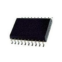
L6201PS STMicroelectronics, L6201PS Datasheet - Page 14

L6201PS
Manufacturer Part Number
L6201PS
Description
IC DRIVER FULL BRIDGE 20-PWRSOIC
Manufacturer
STMicroelectronics
Type
H Bridger
Datasheet
1.L6201013TR.pdf
(20 pages)
Specifications of L6201PS
Input Type
Non-Inverting
Number Of Outputs
2
On-state Resistance
300 mOhm
Current - Output / Channel
4A
Current - Peak Output
5A
Voltage - Supply
12 V ~ 48 V
Operating Temperature
-40°C ~ 150°C
Mounting Type
Surface Mount
Package / Case
PowerSO-20 Exposed Bottom Pad
Operating Supply Voltage
12 V to 48 V
Supply Current
0.015 A
Mounting Style
SMD/SMT
Motor Type
Full Bridge
No. Of Outputs
2
Output Current
5A
Output Voltage
60V
Supply Voltage Range
12V To 48V
Driver Case Style
SOIC
No. Of Pins
20
Operating Temperature Range
-40°C To +150°C
Rohs Compliant
Yes
Operating Current
15mA
Operating Temperature Classification
Automotive
Package Type
PowerSO
Operating Supply Voltage (min)
12V
Operating Supply Voltage (typ)
36V
Operating Supply Voltage (max)
48V
Lead Free Status / RoHS Status
Lead free / RoHS Compliant
Other names
497-1419-5
Available stocks
Company
Part Number
Manufacturer
Quantity
Price
Company:
Part Number:
L6201PS
Manufacturer:
STMicroelectronics
Quantity:
135
Part Number:
L6201PSTR
Manufacturer:
SOIC20
Quantity:
20 000
Company:
Part Number:
L6201PSTR-ST
Manufacturer:
ST
Quantity:
6
L6201 - L6202 - L6203
It could be requested to drive a motor at V
than the minimum recommended one of 12V
(See Electrical Characteristics); in this case, by
accepting a possible small increas in the R
resistance of the power output transistors at the
lowest Supply Voltage value, may be a good solu-
tion the one shown in Fig. 20.
Figure 20: L6201/1P/2/3 Used at a Supply Volt-
THERMAL CHARACTERISTICS
Thanks to the high efficiency of this device, often
a true heatsink is not needed or it is simply ob-
tained by means of a copper side on the P.C.B.
(L6201/2).
Under heavy conditions, the L6203 needs a suit-
able cooling.
By using two square copper sides in a similar way
as it shown in Fig. 23, Fig. 21 indicates how to
choose the on board heatsink area when the
L6201 total power dissipation is known since:
Figure 22 shows the Transient Thermal Resis-
tance vs. a single pulse time width.
Figure 23 and 24 refer to the L6202.
For the Multiwatt L6203 addition information is
given by Figure 25 (Thermal Resistance Junction-
Ambient vs. Total Power Dissipation) and Figure
26 (Peak Transient Thermal Resistance vs. Re-
petitive Pulse Width) while Figure 27 refers to the
single pulse Transient Thermal Resistance.
14/20
R
Th j-amb
age Range Between 9 and 18V
= (T
j max.
L6201
L6201PS
L6202
L6203
– T
amb max
) / P
tot
S
DS (ON)
lower
Figure 21: Typical R
Figure 22: Typical Transient R
Figurre 23: Typical R
Heatsink Area (L6201)
Condition (L6201)
Square Heatsink (L6202)
Th J-amb
Th J-amb
vs. "On Board"
vs. Two "On Board"
TH
in Single Pulse


